Capacitive MEMS sensor device

A sensor device, capacitive technology, applied in the direction of sensors, sensor types, electrostatic sensors, etc.

Active Publication Date: 2009-05-27
III HLDG 6
View PDF3 Cites 12 Cited by
  • Summary
  • Abstract
  • Description
  • Claims
  • Application Information

AI Technical Summary

Problems solved by technology

[0011] In conclusion, US 2006 / 0008097 A1 does not provide a complete and / or optimal solution to the (proximity) adhesion problem of films

Method used


Image

  • Capacitive MEMS sensor device
  • Capacitive MEMS sensor device
  • Capacitive MEMS sensor device

Examples


Embodiment Construction

[0042] In the following text, a MEMS microphone is generally described as an exemplary embodiment of the invention. However, the invention is generally also applicable to all capacitive MEMS sensors, not limited to MEMS microphones.

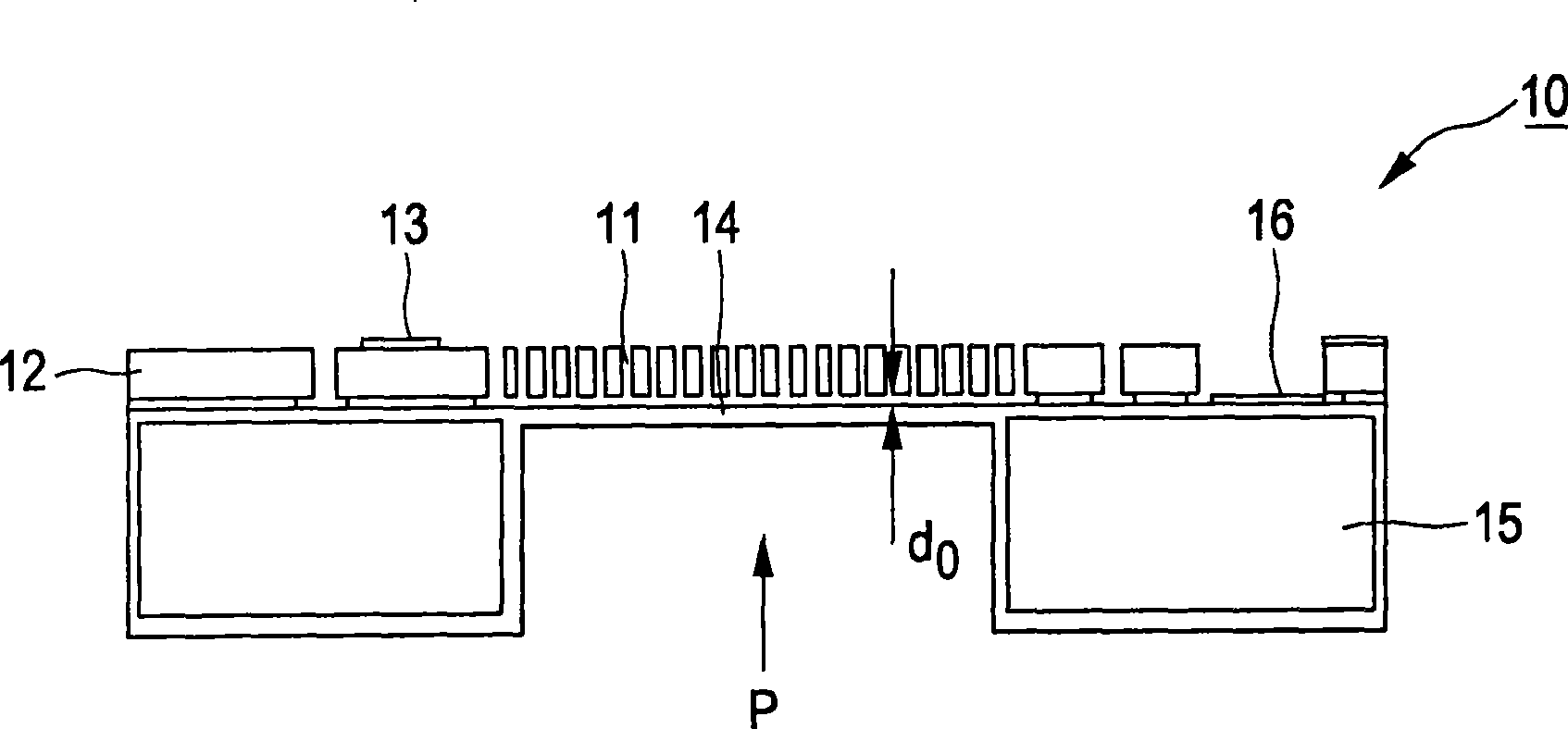
[0043] figure 1 The principle of the capacitive MEMS sensor 10 is shown, and the capacitive MEMS sensor is used to convert the mechanical quantity P (such as the incident sound pressure) into the change of the capacitance value, and the change of the capacitance value is obtained by changing the capacitance between the capacitor plates 11, 14. distance is realized. The capacitor includes two parallel plates, specifically: a rigid plate 11 fixed on a first frame 12 and connected to an electrical contact assembly 13; Forms a rigid unit, but is electrically isolated from the first frame) and is connected to the other plate 14 (in particular the membrane) of the electrical contact assembly 16 . The latter plate 14 moves or bends under the influenc...


PUM


Abstract

The present invention relates to a capacitive MEMS sensor device for sensing a mechanical quantity. To provide such a capacitive MEMS sensor device which enables fast recovery from (near) sticking after a mechanical overload situation it is proposed that the sensor device comprises: - a first bias voltage unit (V1) for supplying a first bias voltage (Vbias 1) to a first plate of said MEMS sensing element, - a second bias voltage unit (V2) for supplying a second bias voltage (Vbias2) to the second plate of said MEMS sensing element, - a signal processing (20) unit for processing said electrical quantity into an output signal (VOUT), - a comparator unit (21) for comparing said output (VOUT) signal to a reference signal (Vref) for detection of an overload condition of said MEMS sensing element (10) and for outputting a comparator signal, - a control unit (22) for controlling the discharge of said MEMS sensing element (10) in case of an overload condition signalled by said comparator signal by connecting, in case of an overload condition, said first plate to a first discharge terminal (D) during a first time interval (T1) and said second plate to a second discharge terminal (D) during a second time interval (T2).

Description

technical field [0001] The present invention relates to capacitive MEMS sensor devices for sensing mechanical quantities, electronic circuits for such capacitive MEMS sensor devices, and methods for operating such capacitive MEMS sensor devices. Background technique [0002] Currently, the market for MEMS (Micro-Electro-Mechanical Systems) sensors and actuators is growing rapidly. The present invention relates to capacitive MEMS sensors such as microphones, accelerometers, and pressure sensors. Typically, such MEMS sensors include a capacitor with two parallel plates. For example, one of the rigid plates is fixed on the frame, and the other plate (such as a membrane) is moved or bent under the influence of the mechanical quantity to be measured (such as acoustic (air) pressure or acceleration). A change in the distance between the plates will result in a change in the capacitance value (that is, the electrical signal that can be measured and processed). [0003] Depending...

Claims


Application Information

Patent Timeline
Patent Type & Authority Applications(China)
IPC IPC(8): G01D5/241H04R3/00G01D3/08G01D5/24H04R19/00
CPCG01D5/24H04R19/005H04R3/007G01D3/08G01D5/2417
Inventor 耶罗恩·范登博门
Owner III HLDG 6
Why Eureka
Try Eureka