Technique for producing spherical distributor

A manufacturing process and distributor technology, which is applied in the field of spherical distributor manufacturing technology, can solve the problems that the drill bit cannot be positioned, the groove of the pipe joint and the spherical surface are difficult to match, etc., and achieve the effect of solving localization and saving manufacturing costs

Active Publication Date: 2009-06-03
SHANGHAI BOILER WORKS
View PDF0 Cites 5 Cited by
  • Summary
  • Abstract
  • Description
  • Claims
  • Application Information

AI Technical Summary

Problems solved by technology

[0003] 1. Drilling on the spherical head: the contact between the miter pipe 3 and the head 2 is a spherical slope, and the drill bit cannot be positioned directly on the spherical slope;
[0004] 2. Processing after fitting the groove of the pipe joint with the spherical surface: because the head 2 is pressed with a steel

Method used


Image

  • Technique for producing spherical distributor
  • Technique for producing spherical distributor
  • Technique for producing spherical distributor

Examples


Embodiment

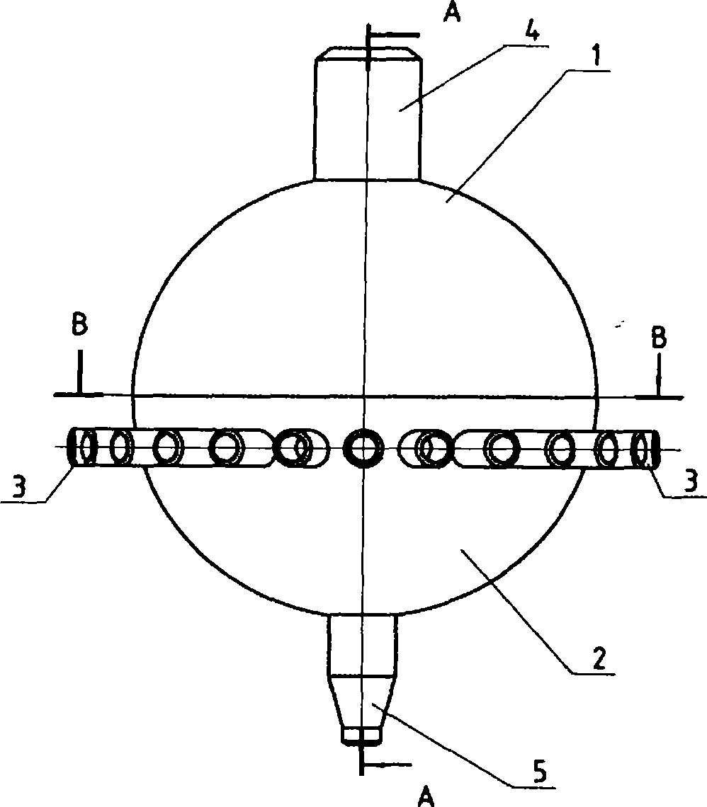
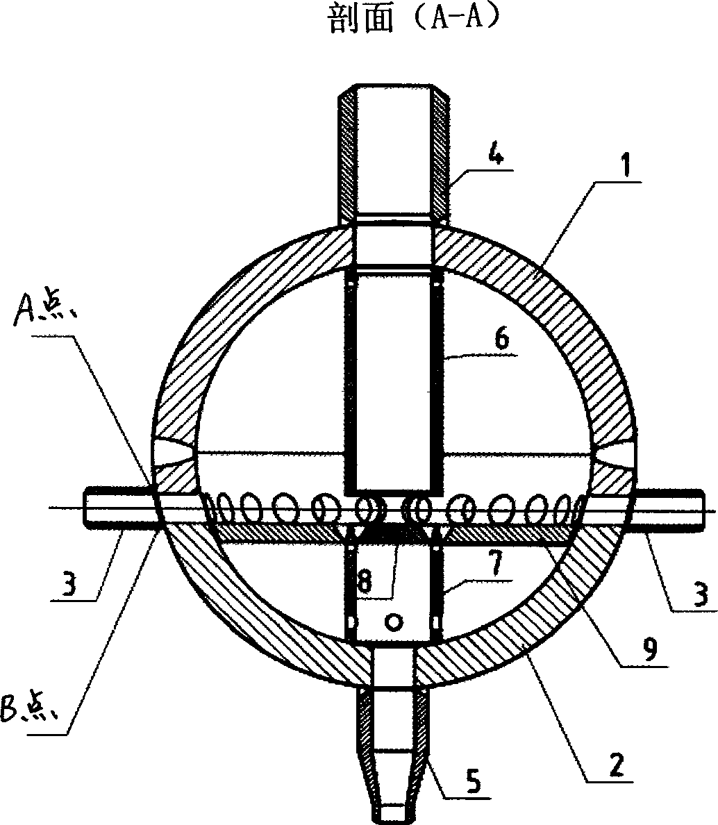
[0024] Such as figure 1 , 2 , Shown in 3, is a schematic diagram of the spherical distributor structure, the present embodiment further illustrates the present invention by manufacturing 16 spherical distributors in Baosteel 4# unit 350MW tower gas and oil fired boilers.

[0025] A spherical distributor manufacturing process is:

[0026] The first step. Install the pipe joint 4 and the inner long pipe 6 inside and outside the top of the upper half head 1 with a diameter of 508mm, so that the pipe joint 4 and the inner long pipe 6 are located on the diameter of the upper half head 1, and the pipe joint 4 has the same diameter as the inner long pipe 6, the diameter is 100mm, the length of the pipe joint 4 is 148mm, and the length of the inner long pipe 6 is 248mm;

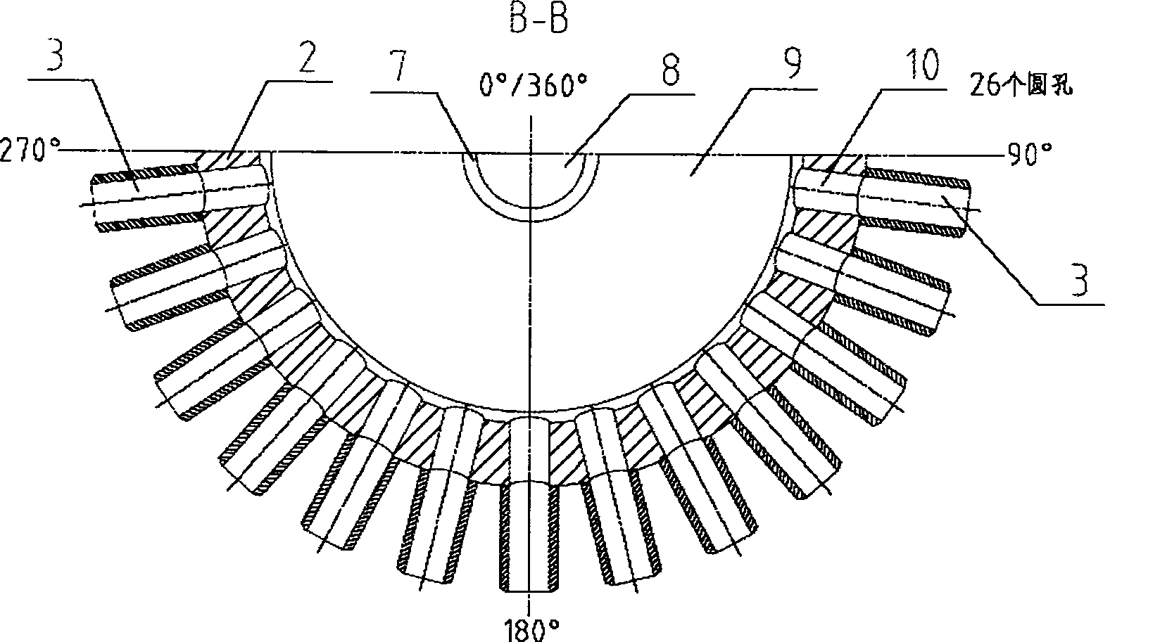
[0027] Step 2. At the ring seam of the lower half of the head with a diameter of 508mm, 60mm away from the centerline of the pipe hole of the miter pipe 3, evenly draw 26 positions that need to be drilled, and at e...


PUM


Abstract

The invention relates to a technique for producing a spherical distributor, the technique is characterized in that a pipe joint and an inner long pipe are respectively arranged inside and outside the top part of an end enclosure in the upper half part; planes are grinded at each A-B position needed to be drilled for drilling and locating; the fall size of A point and B point is obtained by measuring and is used as the fall size for processing the incline at the position of the orifice of an inclined jointing pipe; then the inclined jointing pipe is processed; a tapered pipe is arranged at the bottom part of an end enclosure in the lower half part; then an inner short pipe is arranged in the bottom part of the end enclosure in the lower half part to lead the tapered pipe, the inner short pipe, the pipe joint and the inner long pipe to be arranged on the same line; moreover, an inner piece is welded in the end enclosure of the lower half part; the tapered pipe is respectively welded with each hole in a circle in the end enclosure of the lower half part; finally the end enclosure of the upper half part and the end enclosure of the lower half part are jointed; an automatic-welding circular seam is employed between the end enclosure of the upper half part and the end enclosure of the lower half part. The technique for producing the spherical distributor has the advantages of solving the problem of localization and saving the producing cost.

Description

technical field [0001] The invention relates to a manufacturing process of a spherical distributor, in particular to a manufacturing process of a spherical distributor of a boiler water cooling system, and belongs to the technical field of spherical distributor manufacturing technology. Background technique [0002] At present, the spherical distributor is only used in the three boilers manufactured by the German Babuck company. The domestic boiler industry manufacturers have not manufactured the same type of distributor. I don’t know anything about the technology of the spherical distributor, the drilling of the spherical head, the processing of the pipe joint bevel and the spherical surface, the establishment of the installation sequence to prevent garbage from falling, and the pipe joint after the water pressure test of the distributor. Removal of margin is a key issue to be solved in manufacturing. The existing problems are, such as figure 1 Shown: [0003] 1. Drilling...

Claims


Application Information

Patent Timeline
IPC IPC(8): B23P15/00
Inventor 顾卫红邓建国
Owner SHANGHAI BOILER WORKS
Why Eureka
Try Eureka