Electromagnetic pilot-operated diaphragm valve

A pilot-operated, diaphragm valve technology, applied in the direction of diaphragm valve, diaphragm, valve details, etc., can solve the problems of high minimum opening water pressure, easy water hammer phenomenon, slow water switching speed, etc., to achieve volume reduction, small vibration, The effect of increasing the pressure release speed

Inactive Publication Date: 2009-06-03
朱振连
View PDF0 Cites 18 Cited by
  • Summary
  • Abstract
  • Description
  • Claims
  • Application Information

AI Technical Summary

Problems solved by technology

[0005] The present invention provides an electromagnetic pilot-operated diaphragm valve, the main purpose of which is to overcome the existing electromagnetic pilot-operated diaphragm valve with large volume, high c

Method used


Image

  • Electromagnetic pilot-operated diaphragm valve
  • Electromagnetic pilot-operated diaphragm valve
  • Electromagnetic pilot-operated diaphragm valve

Examples


Embodiment 1

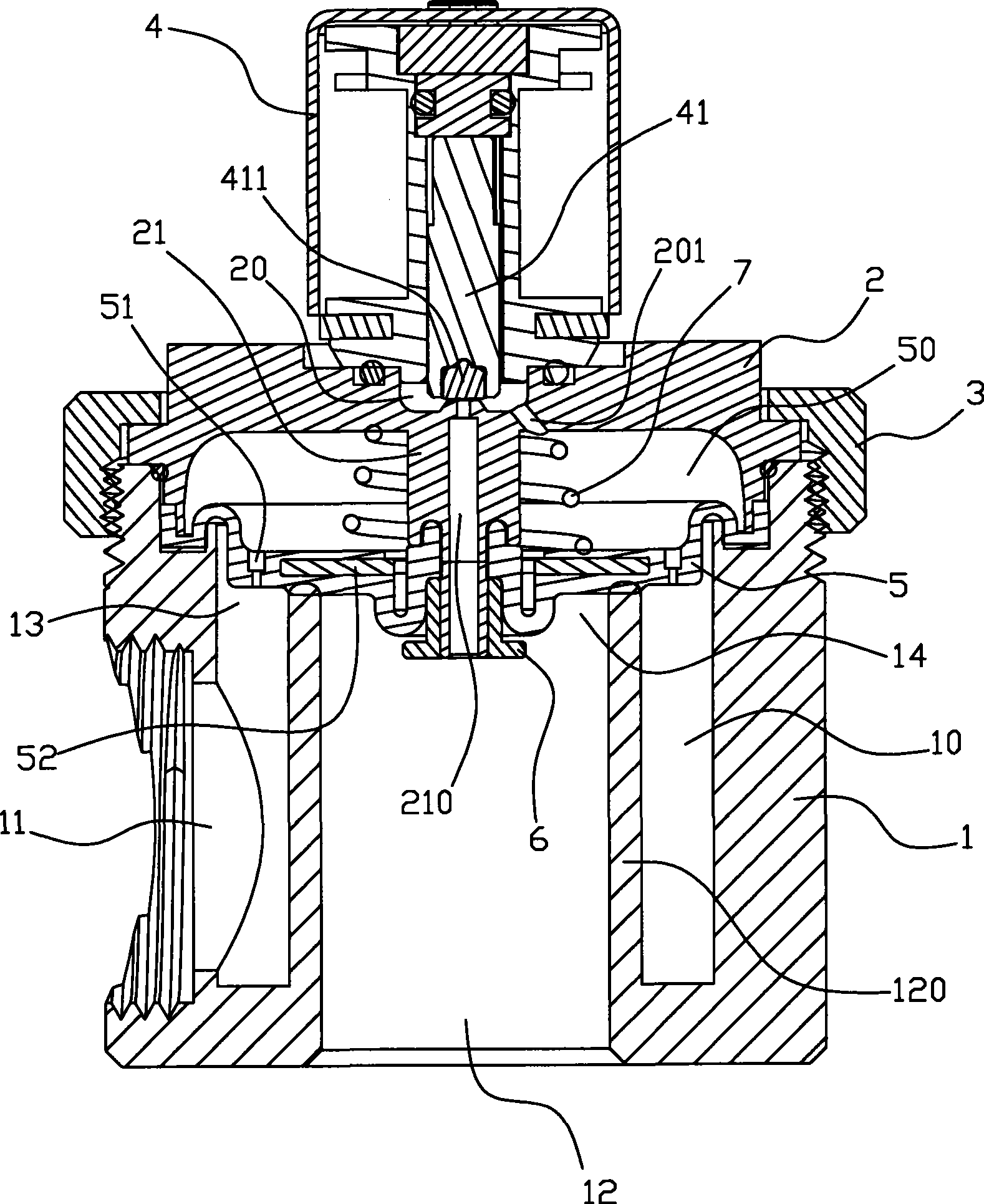
[0020] Solenoid pilot operated diaphragm valve, see figure 1 , its main structure includes valve body 1, valve cover 2, gland 3, solenoid valve 4, diaphragm 5, nut 6 and spring 7. The valve body 1 is provided with a valve chamber 10 and a water inlet 11, a water outlet 12, a control port 13 and a water outlet 14 communicating with the valve chamber. The central axes of the water outlet 12 and the control port are on the same straight line. The central axis of the water outlet 11 is perpendicular to the central axis of the water outlet 12 and the control port. The peripheral edge of the water outlet 12 protrudes into the valve cavity 10 to form a ring wall 120, and the inner end of the ring wall 120 forms the water outlet 14. It can be seen that the water outlet 14 is located between the water inlet 11 and the water outlet 12. , the on-off of the water port 14 can control the on-off of the passage between the water inlet 11 and the water outlet 12 .

[0021] The bonnet 2 is ...

Embodiment 2

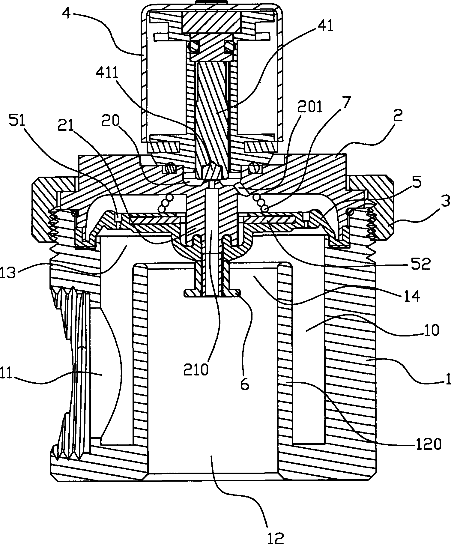
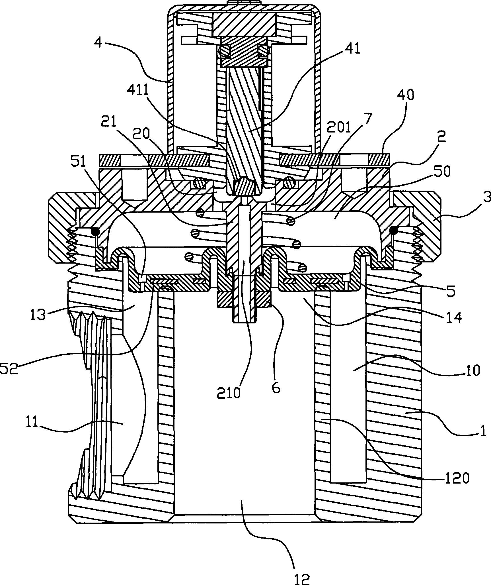
[0027] refer to image 3 and Figure 4 , the structure of this embodiment is basically the same as that of the first embodiment above, the difference is that when the diaphragm valve is in the open or closed state, the shape of the diaphragm 5 of the two is different, and correspondingly, the ring wall 120 and the protrusion 21 of the two are different. The dimensions are also different, and the shapes of the nuts 6 of the two are also different. In addition, the solenoid valve 4 of this embodiment is positioned on the valve cover 2 through a fixing piece 40 .


PUM


Abstract

The invention relates to an electromagnetic pilot-operated diaphragm valve. A water through opening is arranged at a water inlet and a water outlet, and a valve cover is arranged on a control opening; and a diaphragm is arranged between the valve cover and the control opening and can close the water through opening. A water pressure balance cavity is formed between the diaphragm and the valve cover, and the valve cover is provided with a pressure releasing slot which is provided with an electromagnetic valve. The bottom of the pressure releasing slot is provided with a first pressure releasing hole communicated with the water pressure balance cavity, and the diaphragm is provided with a jet orifice. A protruding pole is arranged on the inner surface of the valve cover, the middle part of the diaphragm is fixed on the protruding pole, a second pressure releasing hole is arranged in the protruding pole, and a valve plug of the electromagnetic valve can close the second pressure releasing hole. The water intake aperture of the diaphragm ranges from 15 mm to 20 mm, and the ratio of the areas of the water inlet and the water outlet ranges from 1.5 to 2. The invention can greatly reduce the volume of the whole valve, reduce materials, lower the cost, greatly shorten pressure releasing passages, speed up opening and closing, accomplish normal opening and normal closing at the extremely low water pressure of 0.01 MPa and reduce water hammer, etc.

Description

technical field [0001] The invention relates to a diaphragm valve, in particular to an electromagnetic pilot diaphragm valve. Background technique [0002] Existing diaphragm water valves such as Figure 5 As shown, it includes a valve body 1, a valve cover 2 and a diaphragm 3. The valve body 1 is provided with a water inlet pipe 11, an outlet pipe 12 and a control port 13, and a water outlet 14 is provided between the outlet pipe 12 and the water inlet pipe 11. The diaphragm 3 Set between the valve cover 2 and the control port 13, and above the water port 14, a hydraulic pressure balance chamber 20 is formed between the diaphragm 3 and the valve cover 2, a spring 8 is arranged between the diaphragm 3 and the valve cover 2, and the diaphragm 3 The bottom is provided with a water blocking protrusion 30, which can be blocked on the water outlet 14 to block the passage between the water outlet pipe 12 and the water inlet pipe 11; the inner wall of the water outlet pipe 12 is pr...

Claims


Application Information

Patent Timeline
IPC IPC(8): F16K7/17F16K47/02F16K27/00
Inventor 朱振连
Owner 朱振连
Why Eureka
Try Eureka