A combined relief valve

A pressure relief valve, combined technology, applied in the direction of safety valve, balance valve, valve device, etc., to achieve the effect of shortening the working cycle, convenient operation and maintenance, and reducing the speed of temperature rise

Active Publication Date: 2017-04-19
天津帝广机电设备有限公司
View PDF7 Cites 0 Cited by
  • Summary
  • Abstract
  • Description
  • Claims
  • Application Information

AI Technical Summary

Problems solved by technology

[0003] The problem to be solved by the present invention is to provide a combined pressure relief valve with a two-stage combined pressure relief system and supplementary manual pressure relief for the shortcomings of the existing single-stage hydraulic valves

Method used


Image

  • A combined relief valve
  • A combined relief valve

Examples


Embodiment Construction

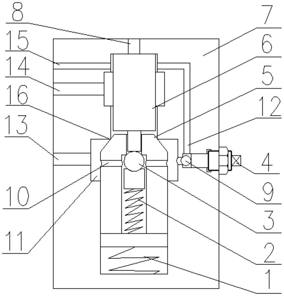
[0019] Such as figure 1 As shown, a combined pressure relief valve related to the present invention includes a valve body 7, one side of the valve body 7 is provided with a high-pressure oil port 13, a main oil drain port 14 and an auxiliary oil drain port 15, and the top of the valve body 7 is provided with There is a control oil port 8, the valve body 7 is provided with a main oil passage 11 and an auxiliary oil passage 12, the main oil passage 11 is connected to the high pressure oil port 13 and the main drain port 14, and the auxiliary oil passage 12 is connected to the main oil passage 11 and the auxiliary drain Oil port 15, the main oil passage 11 is provided with a spool 5 that can move up and down to control the flow or closure of the main oil passage. A piston 6 is provided between the spool 5 and the control oil port 8. The first steel ball 3, the second spring seat 2 and the first spring seat 1 are arranged, the second spring seat 2 is connected below the first stee...


PUM


Abstract

The invention provides a combined pressure relief valve, which includes a valve core, a manual pressure relief valve, a main oil passage, an auxiliary oil passage, a spring seat and other structures, which can realize primary and secondary pressure relief. Under special circumstances such as power failure, manual pressure relief can be realized. By implementing the invention, when the main oil cylinder of the hydraulic machine releases pressure, the pressure release speed is accelerated, the working cycle is shortened, the valve volume is reduced, and the operation and maintenance are convenient.

Description

technical field [0001] The invention belongs to the field of hydraulic transmission system control, in particular to a combined pressure relief valve. Background technique [0002] Pressure relief valves are generally installed on equipment or pipelines in closed systems to protect equipment and pipelines and prevent accidents. In the prior art, when the main cylinder of the hydraulic machine is releasing pressure, the traditional single-stage pressure relief valve has only one stage of pressure relief, and its pressure relief speed is slow, resulting in slow work speed, low work efficiency, and rapid temperature rise. Increased energy consumption of the cooling system. Contents of the invention [0003] The problem to be solved by the present invention is to provide a combined pressure relief valve with a two-stage combined pressure relief system and supplementary manual pressure relief for the shortcomings of the existing single-stage hydraulic valves. [0004] In orde...

Claims


Application Information

Patent Timeline
Patent Type & Authority Patents(China)
IPC IPC(8): F16K17/08F16K17/168
CPCF16K17/082F16K17/168F16K17/044
Inventor 胡益增
Owner 天津帝广机电设备有限公司
Why Eureka
Try Eureka