
Robot toy and assembling method thereof

An assembly method and robot technology, which can be used in toys, automatic toys, instruments, etc., and can solve problems such as complicated operations.

Inactive Publication Date: 2009-06-10
TOMY CO LTD
View PDF0 Cites 0 Cited by
  • Summary
  • Abstract
  • Description
  • Claims
  • Application Information

AI Technical Summary

Problems solved by technology

[0010] But the work is very complicated
[0011] Such a situation may also occur when there are design errors in the components of the robot toy, etc.

Method used


Image

  • Robot toy and assembling method thereof
  • Robot toy and assembling method thereof
  • Robot toy and assembling method thereof

Examples


Embodiment Construction

[0049] Next, the robot toy according to the present invention will be described.

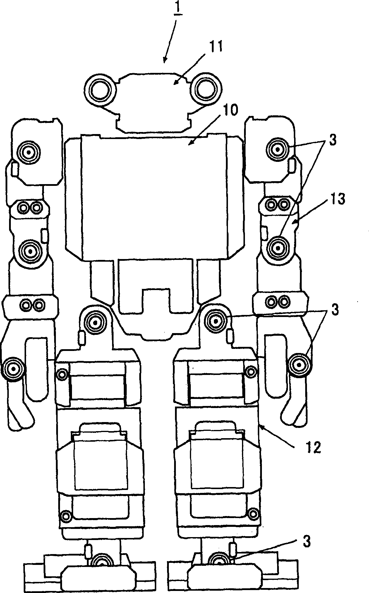
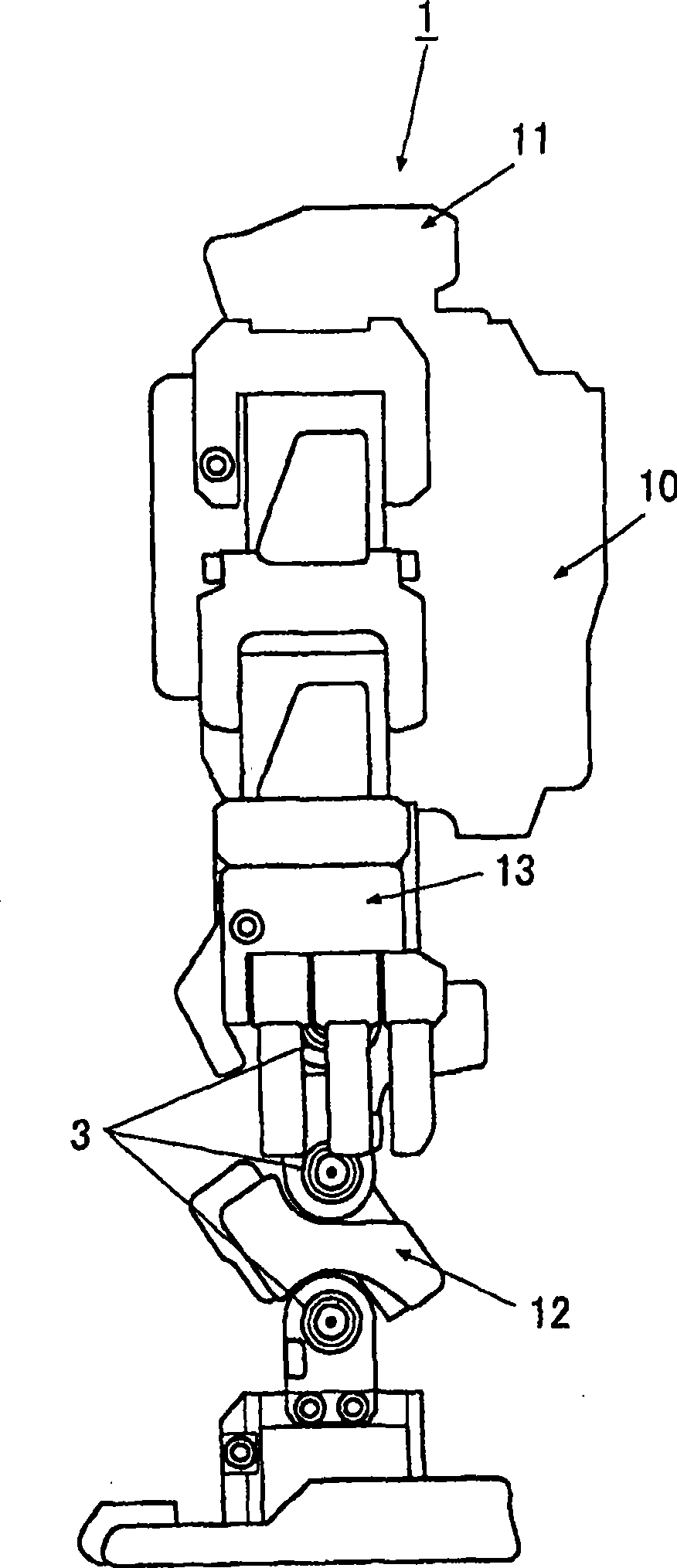
[0050] figure 1 It is a front view of the robot toy 1 in this embodiment, figure 2 is the right side view of the robot toy 1.

[0051] The robot toy 1 is a toy whose operation is remotely controlled by the operation of a controller not shown. Specifically, this robot toy 1 includes: a torso 10, a head 11, a leg 12, and a hand 13. The joints of the legs 12 and the hand 13 are respectively assembled with a robot that is driven according to the operation of the controller. Servo Mechanism 3.

[0052] [Configuration of Servo Mechanism]

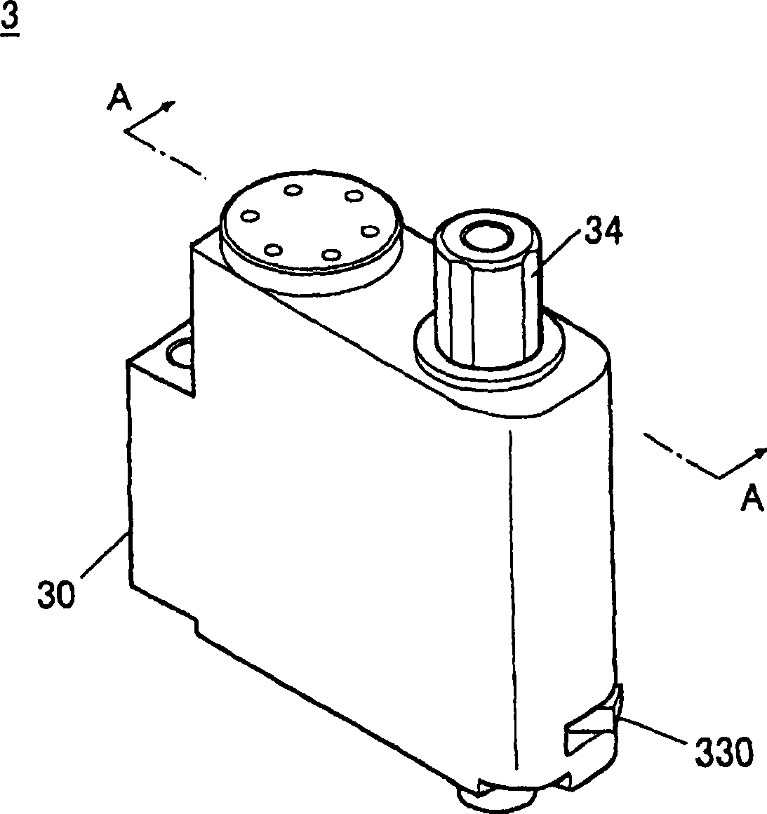
[0053] Such as image 3 , Figure 4 As shown, the servo mechanism 3 rotates and drives the output shaft 34 , and includes a servo motor 31 , a reduction gear mechanism 32 , and a potentiometer 33 inside the housing 30 .

[0054] Among them, the servo motor 31 is used to rotate the reduction gear mechanism 32 .

[0055] The reduction gear mechanism 32 has gear...


PUM


Abstract

The invention provides a robot toy for simply causing the basic initiating position of the robot toy to be accordant with the servo zero position. The robot toy (1) includes: a block (10) including a servo (3); another block (21) connected to the block (10) by fitting an output shaft (34) of the servo into a boss (21a); and a controlling device (100) for controlling the servo; wherein the servo is provided with, a rotating disk (33a) to rotate following the output shaft; a rotating disk (33b) provided facing the rotating disk (33a) to rotate relatively to the rotating disk (33a) in a plane parallel to the rotating disk (33a) according to user operation; and a circuit pattern (8, 9) for detecting a relative angle between reference lines (33c, 33d) on rotating disks (33a, 33b). The controlling device controls the output shaft and the rotating disk (33a) to rotate and controls the servo while a position of the servo when the relative angle is 0 is a center position.

Description

technical field [0001] The present invention relates to a robot toy and an assembly method thereof, more specifically, to a robot toy with a servo mechanism (servo) and an assembly method thereof. Background technique [0002] Conventionally, a robot toy having a structure in which one block is connected to another block by a servo mechanism is known. In this robot toy, the robot toy is generally assembled as follows. [0003] First, the legs of the humanoid robot toy will be described. Here, the constituent elements of the legs include one block to which the RC turbine is attached, and another block to be connected to the one block. In this case, first apply an initial voltage to the signal line of the servo, find the center position (servo zero position), and fit the output shaft of the servo at the basic starting position (home position) of one block and the other block into the boss of another block. In this way, adjacent blocks are preassembled. Thus, the whole leg...

Claims


Application Information

Patent Timeline
Patent Type & Authority Applications(China)
IPC IPC(8): A63H11/00A63H13/00G05D3/12G05B19/18
CPCB25J9/1615G05B19/41805Y10T29/49826Y02P90/02B25J9/06B25J19/02
Inventor 米田阳亮渡边公贵
Owner TOMY CO LTD
Features
  • Generate Ideas
  • Intellectual Property
  • Life Sciences
  • Materials
  • Tech Scout
  • Unparalleled Data Quality
  • Higher Quality Content
  • 60% Fewer Hallucinations
Learn More