Drilling device and drilling method

A technology of coupling device and drilling stand, applied in drilling equipment and methods, supporting device, drilling/drilling equipment, etc., can solve problems such as drill bit stuck, achieve cost saving, high feed rate, high feed rate, etc. powerful effect

Inactive Publication Date: 2009-06-10
BAUER MASCH GMBH
View PDF1 Cites 15 Cited by
  • Summary
  • Abstract
  • Description
  • Claims
  • Application Information

AI Technical Summary

Problems solved by technology

There is a risk of the drill bi

Method used


Image

  • Drilling device and drilling method
  • Drilling device and drilling method
  • Drilling device and drilling method

Examples


Example Embodiment

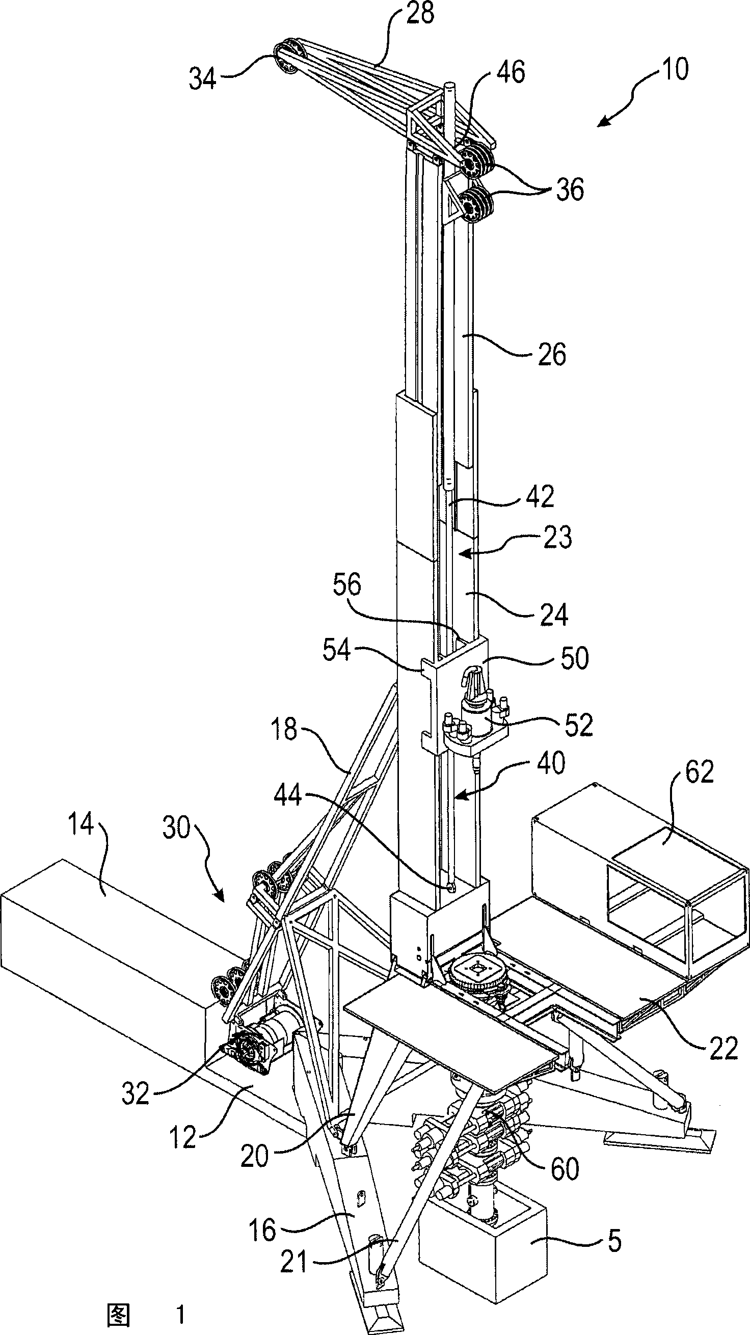
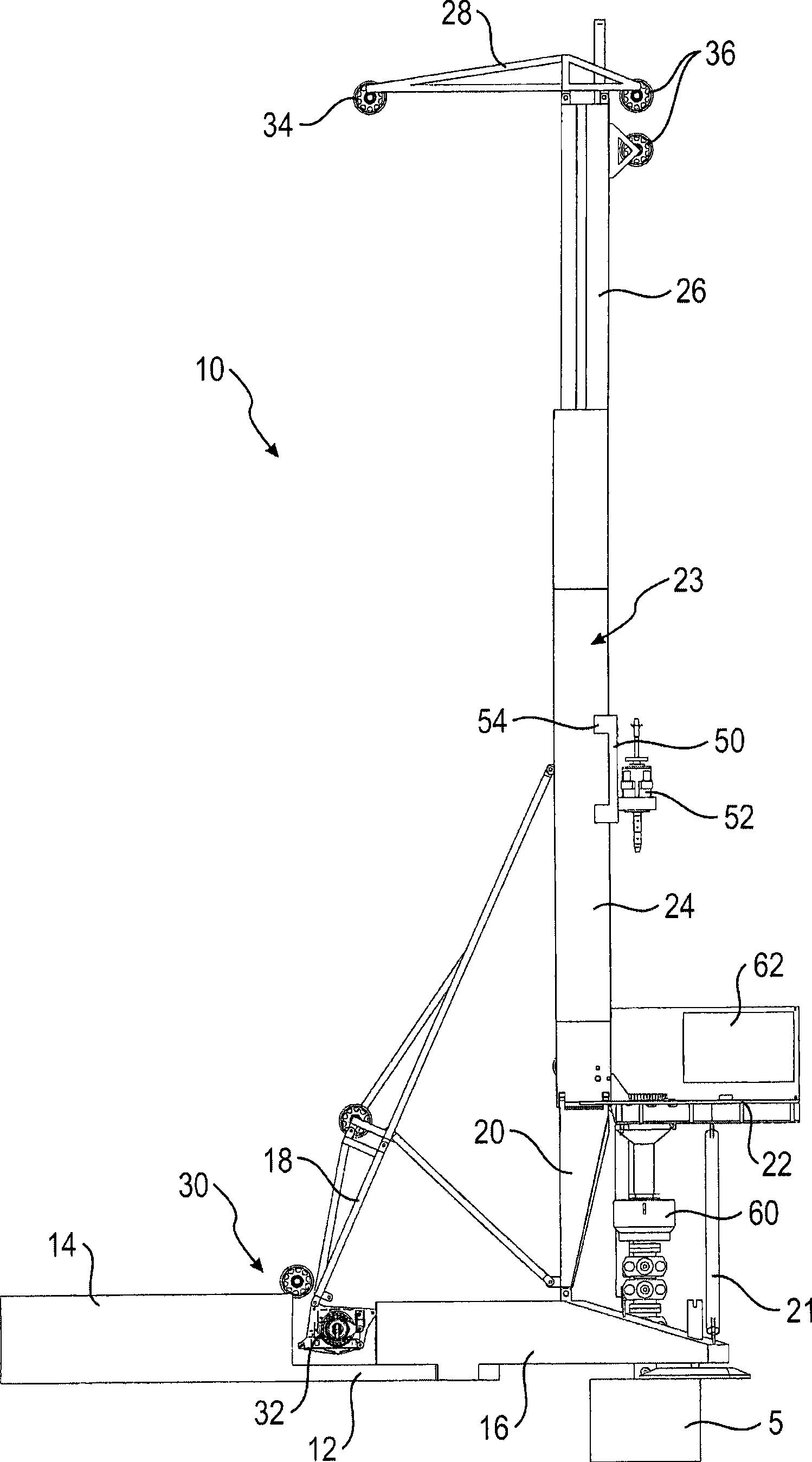
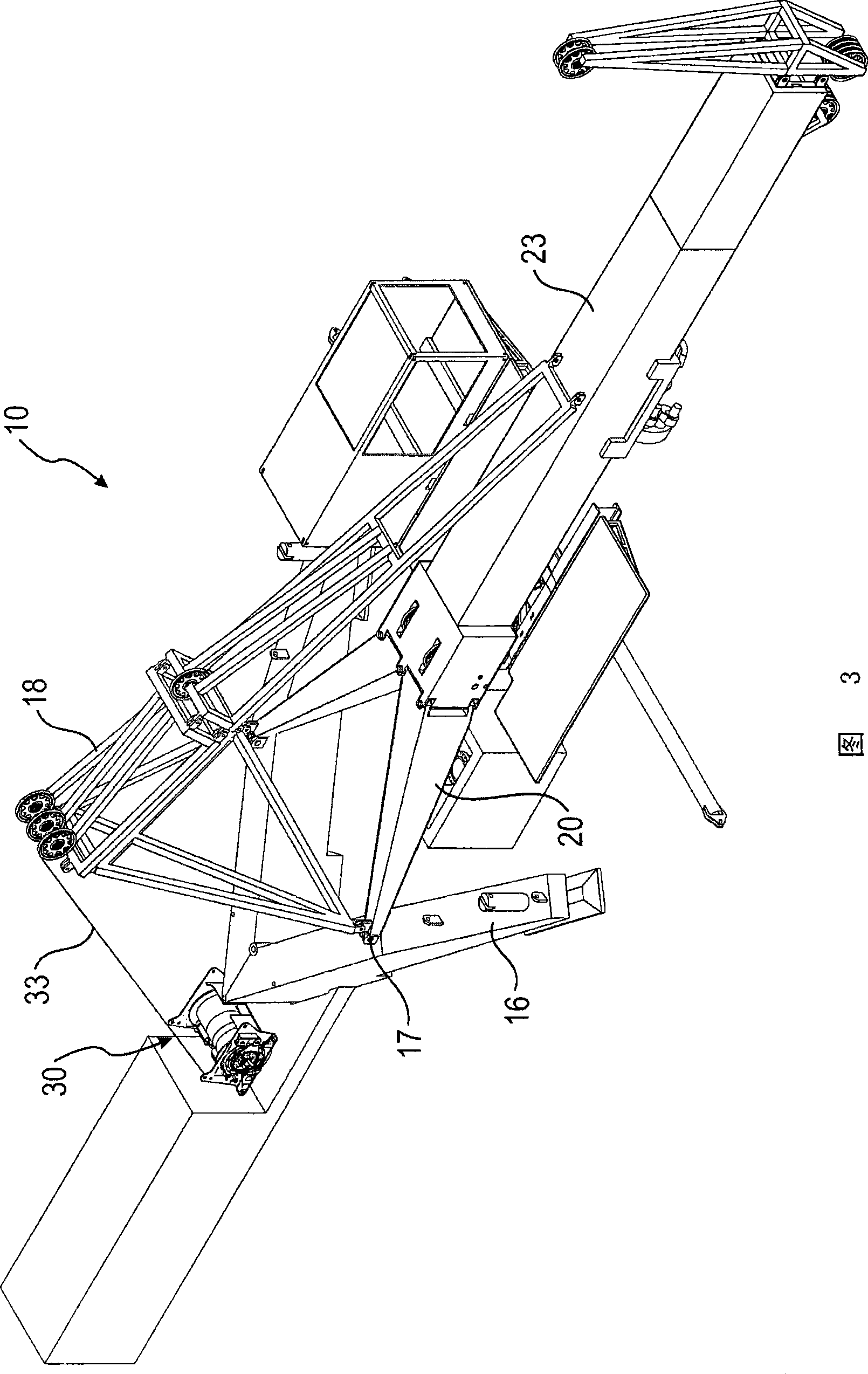
[0028] Figures 1 and 2 show a first drilling device 10 with a base 12 according to the present invention, in which a container-like power unit 14 for energy and hydraulic sources is arranged. At the opposite end of the base 12, a fork-shaped ground support 16 extending around the drilling frame 5 is provided. On the bracket of the fork-shaped ground support 16, the derrick 23 is hinged in a pivotable manner by means of a V-shaped bipod 20. On the rear side of the derrick 23 facing away from the borehole frame 5, said derrick is supported with respect to the base 12 by means of strut equipment 18 with so-called A-trestle.

[0029] On the transition from the derrick 23 to the bipod 20, a substantially horizontally extending drill floor 22 with a box-shaped console 62 is installed. Below the drill floor 22 supported by the strut 21 with respect to the fork-shaped ground support 16, a blowout-preventer 60 with a corresponding clamping device is provided in a known manner for threaded ...


PUM


Abstract

The invention relates to a drilling device and a related drilling method, in which provision is made for a mast, a drilling carriage that is guided along the mast in a displaceable manner and a drive unit for moving the drilling carriage on the mast. In accordance with the invention the drive unit has both a hydraulic cylinder drive and a rope winch drive. The drilling carriage can be coupled with the hydraulic cylinder drive and with the rope winch drive.

Description

technical field [0001] According to the preamble of claim 1 , the invention relates to a drilling arrangement comprising a derrick, a drilling carriage displaceably guided along the derrick, and a drive unit for moving the drilling carriage on the derrick. [0002] The invention also relates to a drilling method for producing a borehole, wherein a first rod and a second rod are moved and in particular introduced into the ground with a drill frame guided on a derrick. Background technique [0003] In drilling rigs of the type employed especially in deep hole drilling, there are generally two main modes of operation. This involves drilling on the one hand and lining the borehole with casing on the other. The first main mode of operation, which requires the largest part of the operating time, is for drilling or extraction of drill pipe sections. In this case, the rod sections must be replaced quickly because the drilling well flushing is interrupted during this time. There i...

Claims


Application Information

Patent Timeline
IPC IPC(8): E21B19/00E21B7/00E21B15/00
CPCE21B15/00E21B19/084E21B7/023B23B35/00B23B39/10B23B41/00
Inventor O·里德S·哈克尔
Owner BAUER MASCH GMBH
Why Eureka
Try Eureka