Method and device for calibrating sensor for measuring angle of mechanical arm or manipulator

A calibration method and calibration device technology, applied in the direction of measuring devices, instruments, etc., can solve the problems of increased production and use costs, inaccurate calibration results, sensor damage, etc., to reduce production and use costs, ensure calibration accuracy, and eliminate errors Effect

Inactive Publication Date: 2009-06-10
SANY HEAVY IND CO LTD (CN)
View PDF0 Cites 21 Cited by
  • Summary
  • Abstract
  • Description
  • Claims
  • Application Information

AI Technical Summary

Problems solved by technology

[0006] First of all, the calibration results of the factory inspection cannot be directly applied to the sensors assembled on the manipulator or manipulator
This is because: the sensor is installed in various ways on the robot arm or manipulator, it is difficult to formulate a standardized installation process; and the calibration table is difficult to fully simulate the condition of the sensor on the robot arm or manipulator, which makes the sensor on the calibration table Calibration results do not always accurately reflect the true condition of the sensor at the time of assembly
[0007] Secondly, it is impossible to calibrate the sensor installed on the robot arm or manipulator
Because the sensors are all performed on the calibration table, it is necessary to repeatedly disassemble and install the sensors on the robotic arm or manipulator, which increases labor intensity and may also cause damage to the sensors
[0008] Again, there is a problem of low confidence in the calibration results
The calibration result depends on the accuracy and reliability of the reference sensor itself. If the reference sensor fails or the accuracy is not high, the calibration result will be inaccurate or even wrong.
[0009] Finally, it is to increase the cost of production and use
The use of a calibration table will undoubtedly increase the cost of production and use, and it is difficult to promote it in the sensor user side; if the calibration table is not used, the reference sensor is installed on the mechanical arm or manipulator instead, which increases the purchase cost of the reference sensor, and increases the installation and removal of the reference sensor. labor costs
[0010] It can be seen that the existing calibration methods and devices are difficult to meet the calibration requirements of sensors on robotic arms or manipulators.

Method used


Image

  • Method and device for calibrating sensor for measuring angle of mechanical arm or manipulator
  • Method and device for calibrating sensor for measuring angle of mechanical arm or manipulator
  • Method and device for calibrating sensor for measuring angle of mechanical arm or manipulator

Examples


Embodiment Construction
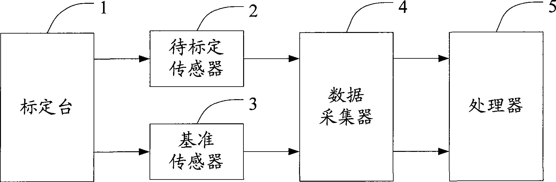
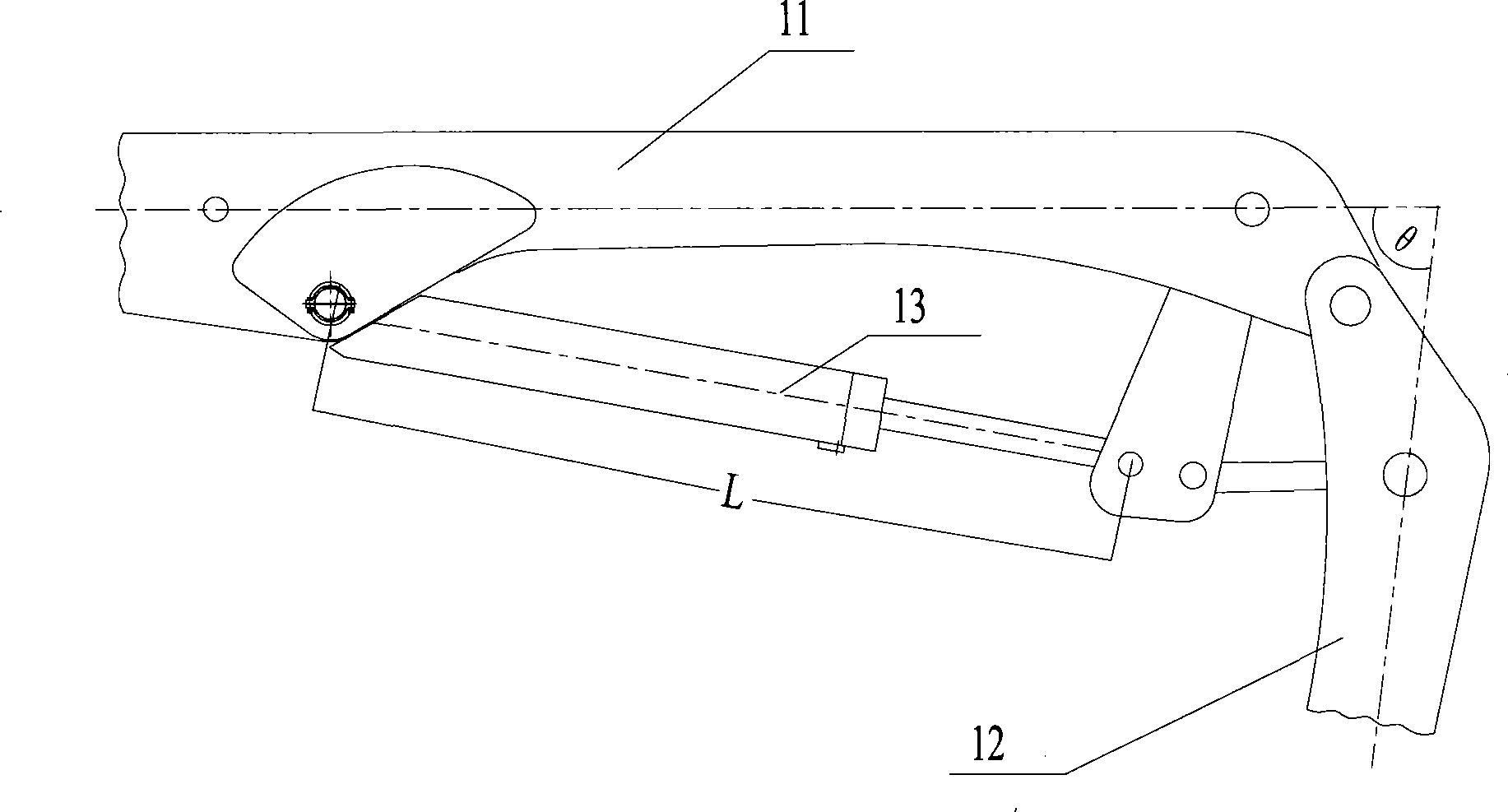
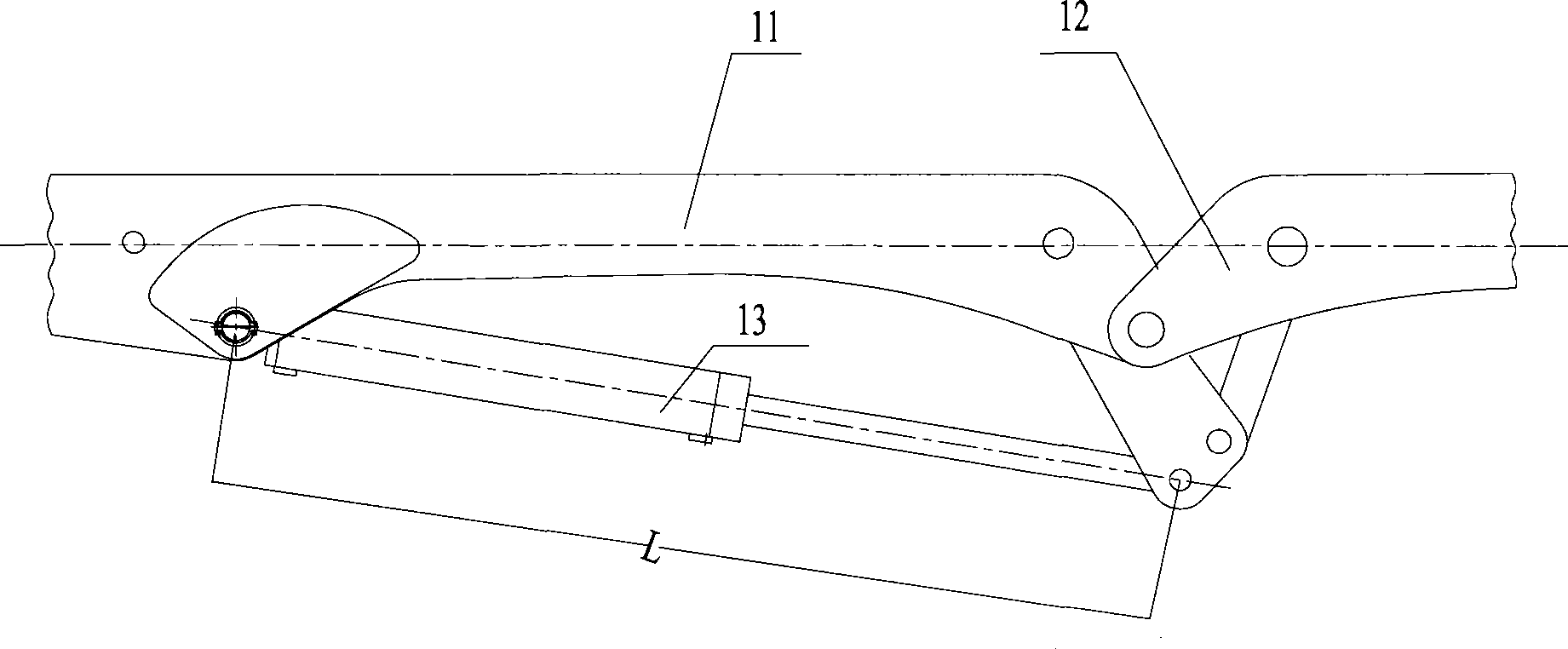
[0032] The basic idea of ​​the present invention is to save the data list between the length of the mechanical arm or the driving mechanism of the mechanical arm and the angle of the mechanical arm or the mechanical arm; by obtaining the length of the mechanical arm or the driving mechanism of the mechanical arm, the corresponding theoretical value of the mechanical arm or the angle of the mechanical arm is obtained, so as to This is used as the calibration reference value of the sensor; compare and analyze the measured value of the sensor with the calibration reference value to complete the calibration of the sensor.

[0033] It can be seen that the key to solving the problem in the present invention is to calibrate the sensor under the premise of installing the sensor on the robot arm or manipulator arbitrarily, so that the real-time measured value returned by the sensor corresponds to the logic value defined in the control process one by one.

[0034] The principle of the pr...


PUM


Abstract

The invention discloses a sensor scaling method for measuring angles of mechanical arm and mechanical hand, comprising the steps of: pre-storing data lists between the mechanical arm and mechanical hand driving mechanism length, between angle of the mechanical arm and angle of the mechanical hand; searching for the data lists by acquiring a measurement value of the sensor to be scaled on the mechanical arm and mechanical hand driving mechanism length, and acquiring theoretical values of the angles of mechanical arm and mechanical hand corresponding to the measurement value of the sensor to be scaled on the mechanical arm and mechanical hand driving mechanism length, as scaled reference values of the sensor to be scaled; comparing and analyzing the measurement value of the sensor to be scaled and the scaled reference values, and scaling the sensor to be scaled. The invention, with no limitation of own installation means of the sensor, can accurately scale when the mechanical arm or mechanical hand is in any status. On this basis, the invention also discloses a sensor scaling device for measuring angles of mechanical arm and mechanical hand.

Description

technical field [0001] The present invention relates to the technical field of testing or calibration of measuring equipment or devices, specifically a sensor calibration method and device for measuring the angle of a mechanical arm or a manipulator, which is mainly suitable for large construction machinery (such as concrete pump trucks, cranes, Excavators, etc.), especially multi-section boom or bending structure of the mechanical arm or robot. Background technique [0002] In intelligent mechanical equipment, the quality of the coordinated motion of each actuator directly affects the quality of the product. For example, when an intelligent concrete pump truck is pouring, if the movement of each section of the boom is uncoordinated, the movement of the end point of the boom will not move according to the predetermined route; this will inevitably affect the quality of pouring, and then affect the quality of the project. cause safety hazards. Therefore, in the process of re...

Claims


Application Information

Patent Timeline
Patent Type & Authority Applications(China)
IPC IPC(8): G01B21/22
Inventor 周翔石培科黄罡
Owner SANY HEAVY IND CO LTD (CN)
Why Eureka
Try Eureka