Laser ranging apparatus and method

A laser ranging and laser technology, which is applied in the field of ranging, can solve the problems of low optical signal intensity, difficulty in receiving and processing, high cost of receiving devices, etc., and achieve the effect of cost saving

Inactive Publication Date: 2009-06-10
FOSHAN PREMIER SCI & TECH CO LTD +1
View PDF3 Cites 46 Cited by
  • Summary
  • Abstract
  • Description
  • Claims
  • Application Information

AI Technical Summary

Problems solved by technology

However, in reflective reception, because the optical signal strength is smaller than that of direct reception, it is quite weak when the distance is long, it is difficult to receive and process, and the cost of the receiving device is expensive

Method used


Image

  • Laser ranging apparatus and method
  • Laser ranging apparatus and method
  • Laser ranging apparatus and method

Examples


Embodiment Construction

[0011] The present invention will be further described in detail below in conjunction with the accompanying drawings.

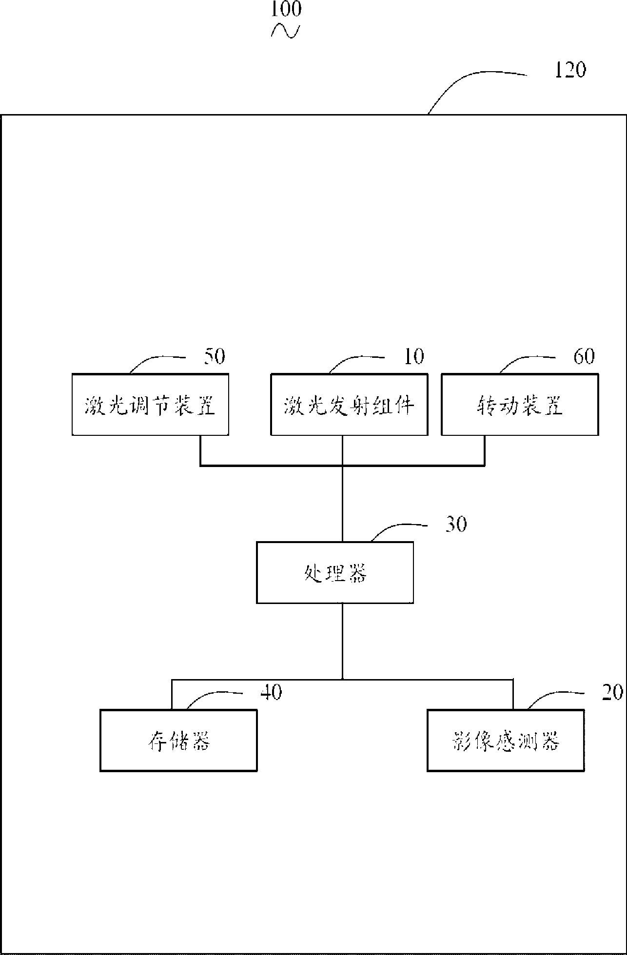
[0012] see figure 1 and figure 2 , the laser distance measuring device 100 can be used for auxiliary measurement of camera devices, distance measurement in automatic mobile devices, application in automobile anti-collision systems, and measurement of cave interior space.

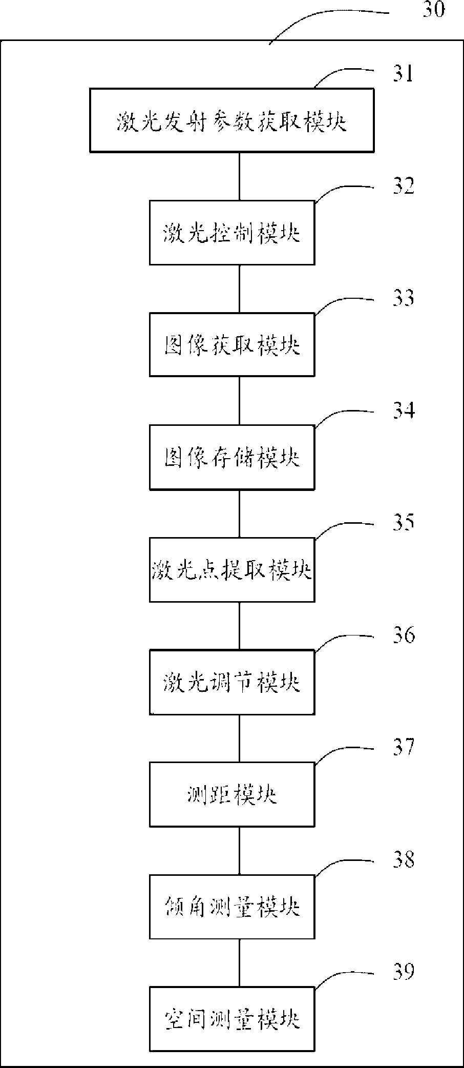
[0013] The laser ranging device 100 includes a laser emitting component 10 , an image sensor 20 , a processor 30 , a memory 40 , a laser adjusting device 50 and a rotating device 60 .

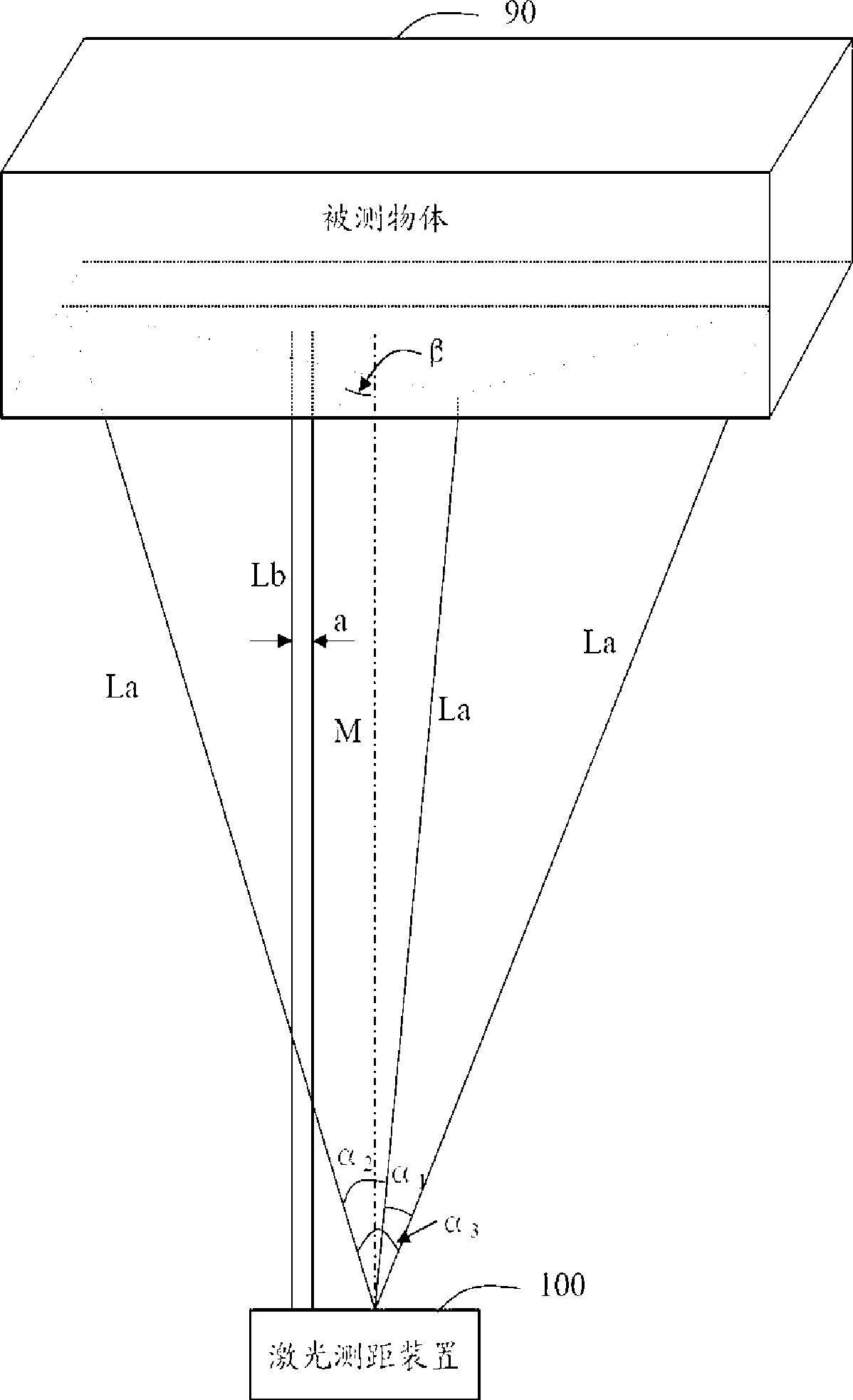
[0014] The laser emitting component 10 emits a plurality of measuring laser beams La radiated from the same point to the surroundings and a scale laser beam Lb parallel to the central axis M of the measuring laser beam La. In this embodiment, the laser emitting assembly 10 emits three measurement laser beams La and two scale laser beams Lb. The measuring laser beam La is radiated from the same point to t...


PUM


Abstract

The invention provides a laser range finding device, including a laser emitting assembly, a video sensor, a processor and a memory. The laser emitting assembly emits a plurality of measuring laser beams that are radiantly projected from the same spot to every direction, and also emits two measuring scale laser beams that are parallel to the central axis of the plurality of measuring laser beams. The processor includes: a laser control module for controlling emission and closing of the laser. A laser emitting parameter acquiring module is used for acquiring an included angle between each two of the measuring laser beams and pitch between the measuring scale laser beams. An image acquiring module is used for acquiring images prior to and subsequent to emission of the laser, and storing the images in the memory. A laser spot extracting module is used for extracting positions of the laser spots where the laser beams are projected on in the image. A range finding module is used for calculating the distance between the laser range finding device and a measured object. In addition, the invention also provides a laser range finding method.

Description

technical field [0001] The invention relates to a ranging technology, in particular to a laser ranging device and method. Background technique [0002] Generally speaking, the main methods of receiving the optical signal of laser ranging are direct reception and reflection reception. In terms of direct reception, due to the high requirements for equipment, most of these equipment are quite expensive, and are mostly used in high-tech fields such as aerospace, and are rarely used in civilian use. At present, the laser ranging technology used for civilian use mostly adopts reflection reception, and takes the average value to measure the distance after multiple reflections in a long period of time. However, during reflective reception, since the optical signal strength is smaller than that of direct reception, it is quite weak when the distance is long, it is difficult to receive and process, and the cost of the receiving device is expensive. Contents of the invention [000...

Claims


Application Information

Patent Timeline
Patent Type & Authority Applications(China)
IPC IPC(8): G01C3/24G01C3/02
Inventor 陈水燕
Owner FOSHAN PREMIER SCI & TECH CO LTD
Why Eureka
Try Eureka