
Flow path control method for material handling system of stock yard

A conveying system and process control technology, applied in the direction of electrical program control, sequence/logic controller program control, etc., can solve the problems of less process, less equipment, more manpower and funds, etc., to save investment and shorten software development the effect of time

Inactive Publication Date: 2009-06-10
WISDRI ENG & RES INC LTD
View PDF0 Cites 5 Cited by
  • Summary
  • Abstract
  • Description
  • Claims
  • Application Information

AI Technical Summary

Problems solved by technology

[0002] At present, there are mainly two methods of process control in raw material yards. One is to use a secondary computer to implement process control using database and high-level language programming. This method is mainly suitable for large-scale raw material yards, with complex systems, many equipment, and many processes; the other The first is to program one by one according to the process, and realize one process and one program. This method is mainly suitable for some small raw material farms, with less equipment, less processes, and a relatively simple system, which is not suitable for large raw material farms.
[0003] The second-level computer system used in the first method is mostly imported from abroad, and more manpower and funds are invested in independent development. At present, the domestic industrial structure is adjusted, the scale of enterprises is getting larger and smaller, and small raw material farms are gradually being eliminated or transformed. Generally do not use the second method

Method used


Image

  • Flow path control method for material handling system of stock yard

Examples


Embodiment Construction

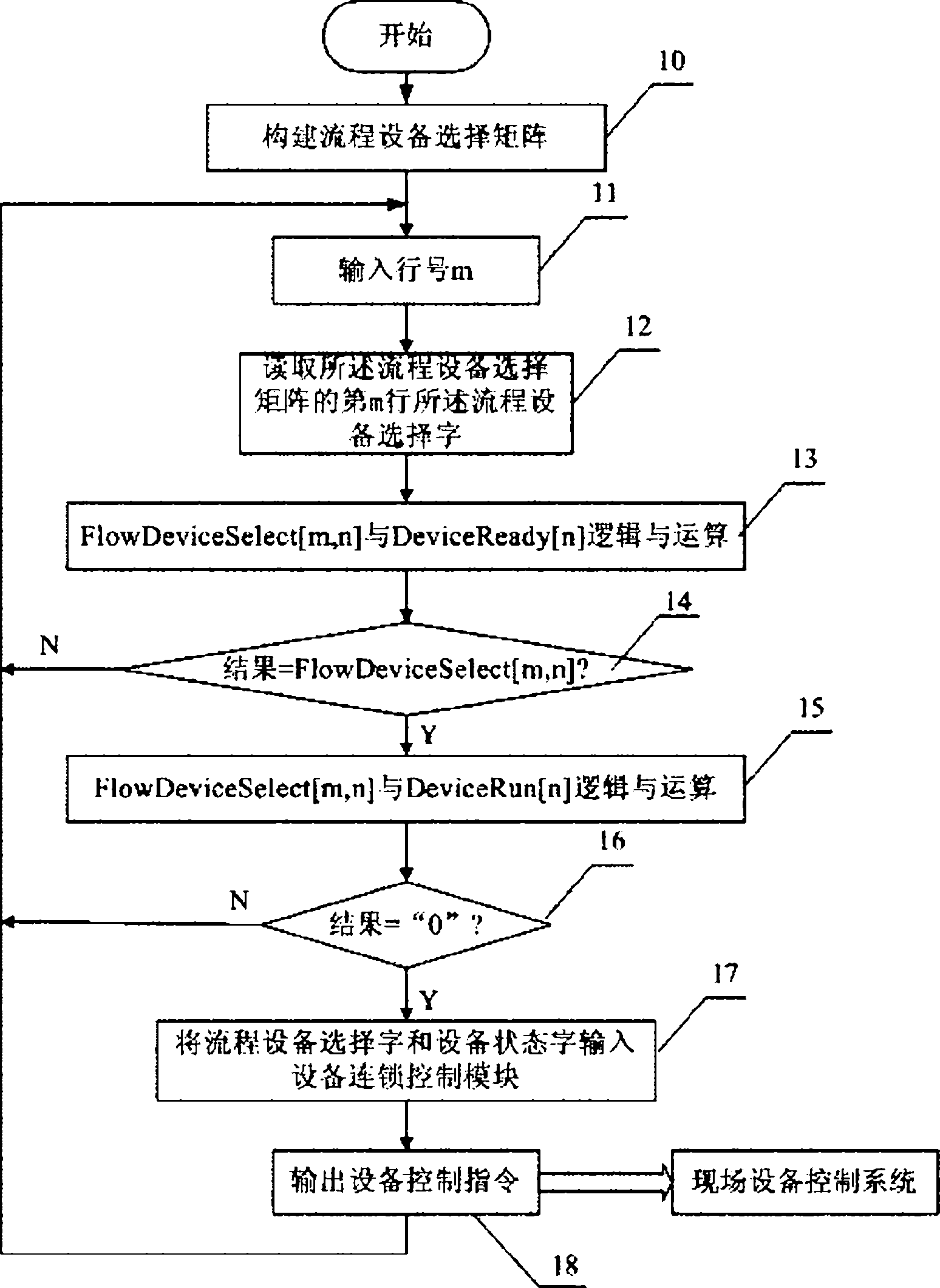
[0018] Such as figure 1 As shown, the system starts and enters step 10 to build a two-dimensional process device selection matrix FlowDeviceSelect[m, n] to store the selection relationship between processes and devices. The row number m of the matrix is ​​used as the process number, and the column number n is used to identify the device , for example, FlowDeviceSelect[21, 30]=1 means that the No. 21 process selects the No. 30 device.

[0019] Go to step 11 and enter the process number m;

[0020] Enter step 12, read the process equipment selection word in the mth row of the process equipment selection matrix,

[0021] Step 13, use matrix logic operation to deal with the interlocking relationship between the processes, and perform the logic "AND" operation of the flow device selection word FlowDeviceSelect[m, n] and the device status word DeviceReady[n],

[0022] Step 14, judge whether the result is equal to FlowDeviceSelectm, n], if not in step 14, return to step 11.

[002...


PUM


Abstract

The invention relates to a method for controlling a material transporting system of a stock yard of a large-scale industrial enterprise. Flow equipment is constructed to select the selectional relation between a matrix storage flow and the equipment; a line number of a matrix is used as a flow number; and a row number is used to identify the equipment. Then the flow number is input; a flow equipment optional word is extracted from a flow equipment selection matrix; the flow equipment optional word and an equipment status word are subjected to logical operation; a calculation result is used to judge whether the flow is ready; if the flow is not ready, the flow number is re-input to select other flows; if the flow shows ready, the flow equipment optional word and the equipment status word are assigned to an equipment interlocking control module; and an equipment interlocking control program outputs the equipment status word. The equipment status word transmits a startup control signal and a stoppage control signal of the equipment, thereby completing the flow control. The method can save the investment of a secondary computer for controlling materials in the stock yard, can be conveniently realized through programming in a PLC or other logical controllers and shorten time for software development.

Description

technical field [0001] The invention relates to the control of the material conveying system in the raw material field of large-scale factories and mines. Background technique [0002] At present, there are mainly two methods of process control in raw material yards. One is to use a secondary computer to implement process control using database and high-level language programming. This method is mainly suitable for large-scale raw material yards, with complex systems, many equipment, and many processes; the other The first is to program one by one according to the process, and realize one process by one program. This method is mainly suitable for some small raw material farms, with less equipment, fewer processes, and a simpler system, which is not suitable for large raw material farms. [0003] The second-level computer system used in the first method is mostly imported from abroad, and more manpower and funds are invested in independent development. At present, the domesti...

Claims


Application Information

Patent Timeline
IPC IPC(8): G05B19/04
Inventor 路万林李敏张华
Owner WISDRI ENG & RES INC LTD
Learn More