Eureka AIR delivers breakthrough ideas for toughest innovation challenges, trusted by R&D personnel around the world.

Solid electrolytic capacitor

A technology of solid electrolysis and capacitors, which is applied in the direction of solid electrolytic capacitors, electrolytic capacitors, capacitors, etc., can solve the problems such as the decline of the yield of solid electrolytic capacitors 101

Active Publication Date: 2009-06-10
SANYO ELECTRIC CO LTD
View PDF2 Cites 1 Cited by
  • Summary
  • Abstract
  • Description
  • Claims
  • Application Information

AI Technical Summary

Problems solved by technology

In addition, since there are variations in the welding position and strength when the support member 180 is welded to the anode portion 104 of the capacitor element 102, the capacitor element 102 cannot be mounted on the lead frame with high precision, and solid electrolysis often occurs. Capacitor 101 yield drops

Method used


Image

  • Solid electrolytic capacitor
  • Solid electrolytic capacitor
  • Solid electrolytic capacitor

Examples


Embodiment Construction

[0026]

Solid Electrolytic Capacitor

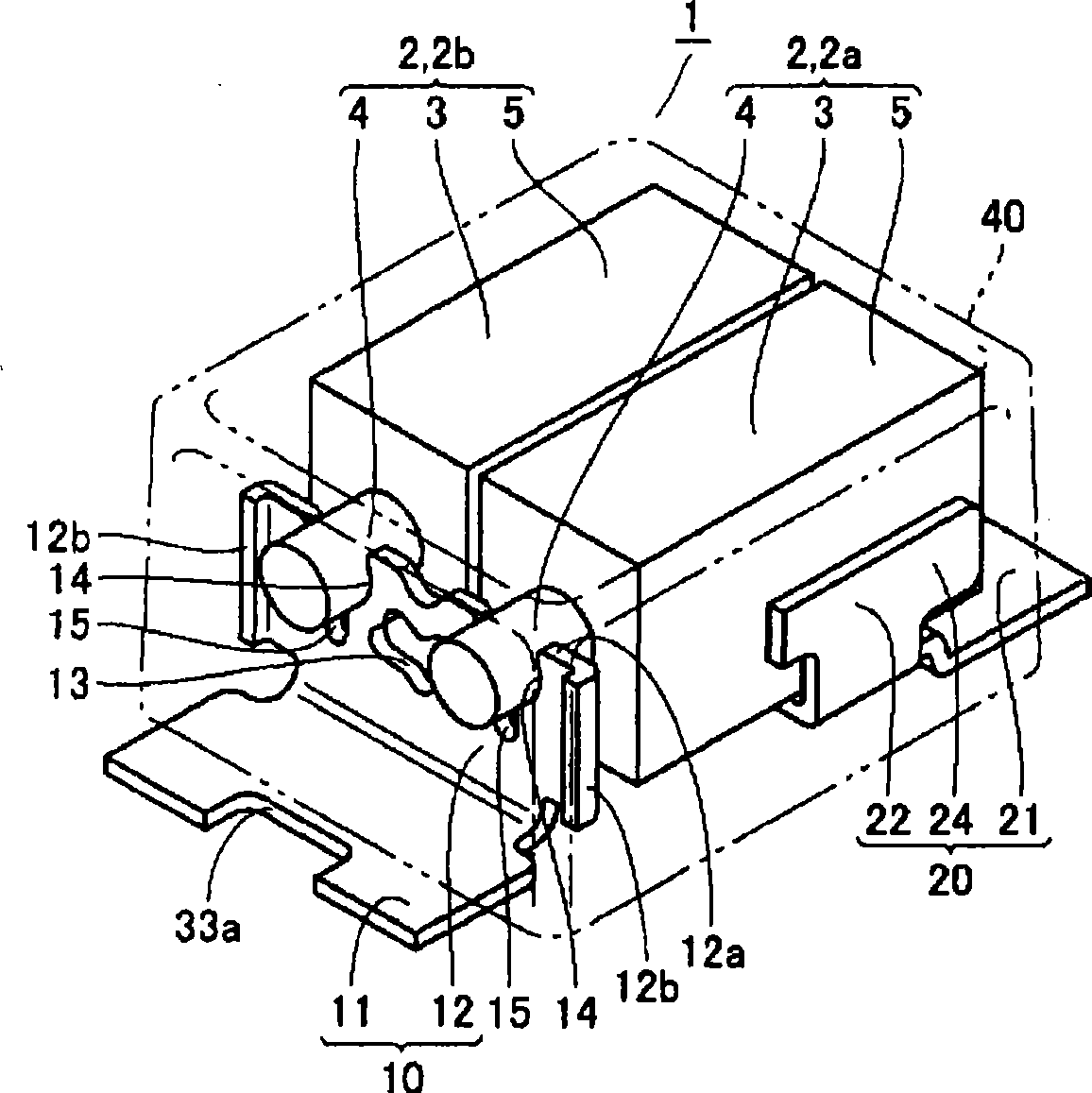
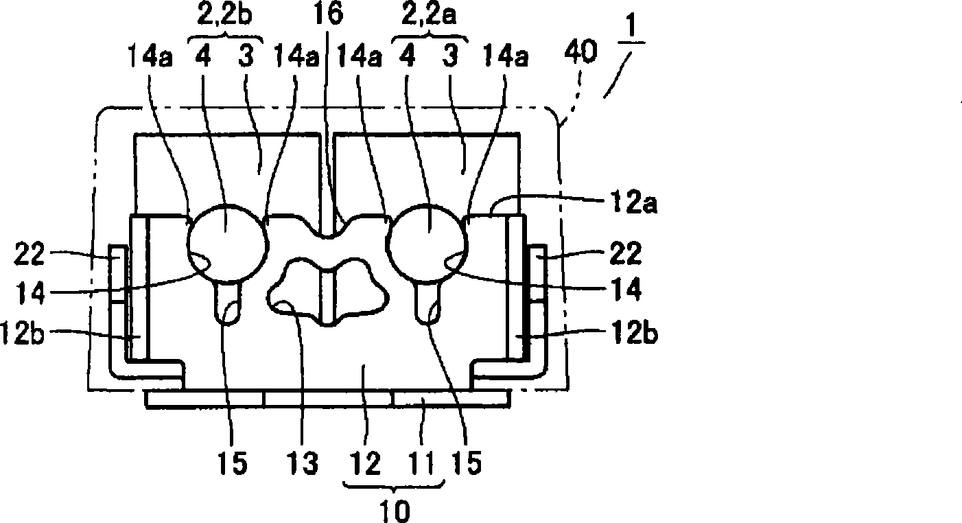
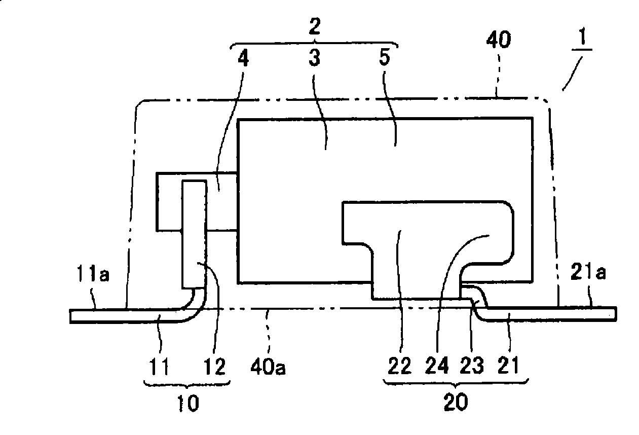
Next, a solid electrolytic capacitor according to an embodiment of the present invention will be described. Such as Figure 1 to Figure 5 As shown, a solid electrolytic capacitor 1 includes two capacitor elements 2, 2a, 2b, an anode lead frame 10, a cathode lead frame 20, and a molding resin 40 sealing them. In the capacitor element 2 , an anode portion 4 is formed protruding from a substantially columnar (cuboid) anode body 3 , and a cathode portion 5 is formed on the outer peripheral surface of the anode body 3 . In addition, the anode portions 4 of the two capacitor elements 2a and 2b are provided facing the same direction.

[0027]

The anode lead frame 10 includes an anode terminal portion 11 and a standing portion 12 . The anode terminal portion 11 is exposed along the bottom surface a of the mold resin 40 . The upper surface 11a of the anode terminal part 11 is directly connected to the bottom surface 40a of the molding resin ...


PUM


Abstract

A solid electrolytic capacitor includes a capacitor element, an anode lead frame, a cathode lead frame, and a mold resin portion. The anode lead frame includes an anode terminal portion and a rising portion. The rising portion is formed integral with the anode terminal portion, and extends from the anode terminal portion through the mold resin portion toward the anode portion, and is connected to the anode portion. At the rising portion, a catching recess and a holding portion are formed and, in addition, a first slit is formed downward from the catching recess. Thus, a solid electrolytic capacitor allowing highly accurate and reliable attachment of the capacitor element to the lead frame without using any additional member is provided.

Description

technical field [0001] The present invention relates to a solid electrolytic capacitor, and more particularly to a solid electrolytic capacitor in which a capacitor element is mounted on a predetermined lead frame and sealed with a molding resin. Background technique [0002] Solid electrolytic capacitors are one of the electronic components that can be mounted on the surface of a printed component substrate or the like. Such as Figure 44 or Figure 45 As shown, such a solid electrolytic capacitor 101 includes a capacitor element 102, an anode lead frame 110, a cathode lead frame 120, and a molding resin 140 sealing them. In the capacitor element 102 , an anode portion 104 is formed to protrude from a substantially columnar (cuboid) anode body 103 , and a cathode portion 105 is formed on the outer peripheral surface of the anode body 103 . The anode lead frame 110 is electrically connected to the anode part 104 through the support part 180 ; the cathode lead frame 120...

Claims


Application Information

Patent Timeline
Patent Type & Authority Applications(China)
IPC IPC(8): H01G9/004H01G9/008H01G9/12H01G9/15
CPCH01G9/14H01G9/012H01G9/004H01G9/08H01G9/15
Inventor 松冈桂子梅田昌志
Owner SANYO ELECTRIC CO LTD
Why Eureka
Eureka Blog
Learn More