Suction apparatus and suction method using such suction apparatus

A technology of adsorption device and suction hole, applied in the field of adsorption, can solve problems such as surface scratches of resin molded products, and achieve the effect of improving adsorption force

Inactive Publication Date: 2009-06-10
HONDA MOTOR CO LTD
View PDF2 Cites 15 Cited by
  • Summary
  • Abstract
  • Description
  • Claims
  • Application Information

AI Technical Summary

Problems solved by technology

[0005] However, although any of the above-mentioned techniques can change the direction of the suction surface of the suction pad (suction pad) and have the advantage of finally ensuring the holding function, when the suction pad comes into contact with the curved portion or inclined portion of the workpiece, the After abutment until the suction buffer plate is aligned with the suction surface, it is necessary to perform suction while sliding along the oblique direction of the workpiece surface. Therefore, there may be disadvantages such as scratches on the surface of the resin molded product.

Method used


Image

  • Suction apparatus and suction method using such suction apparatus
  • Suction apparatus and suction method using such suction apparatus
  • Suction apparatus and suction method using such suction apparatus

Examples


Embodiment Construction

[0017] Embodiments of the present invention will be described with reference to the drawings.

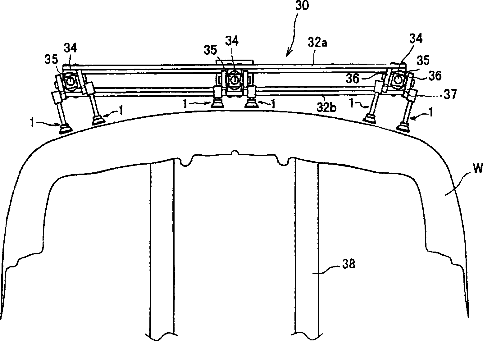
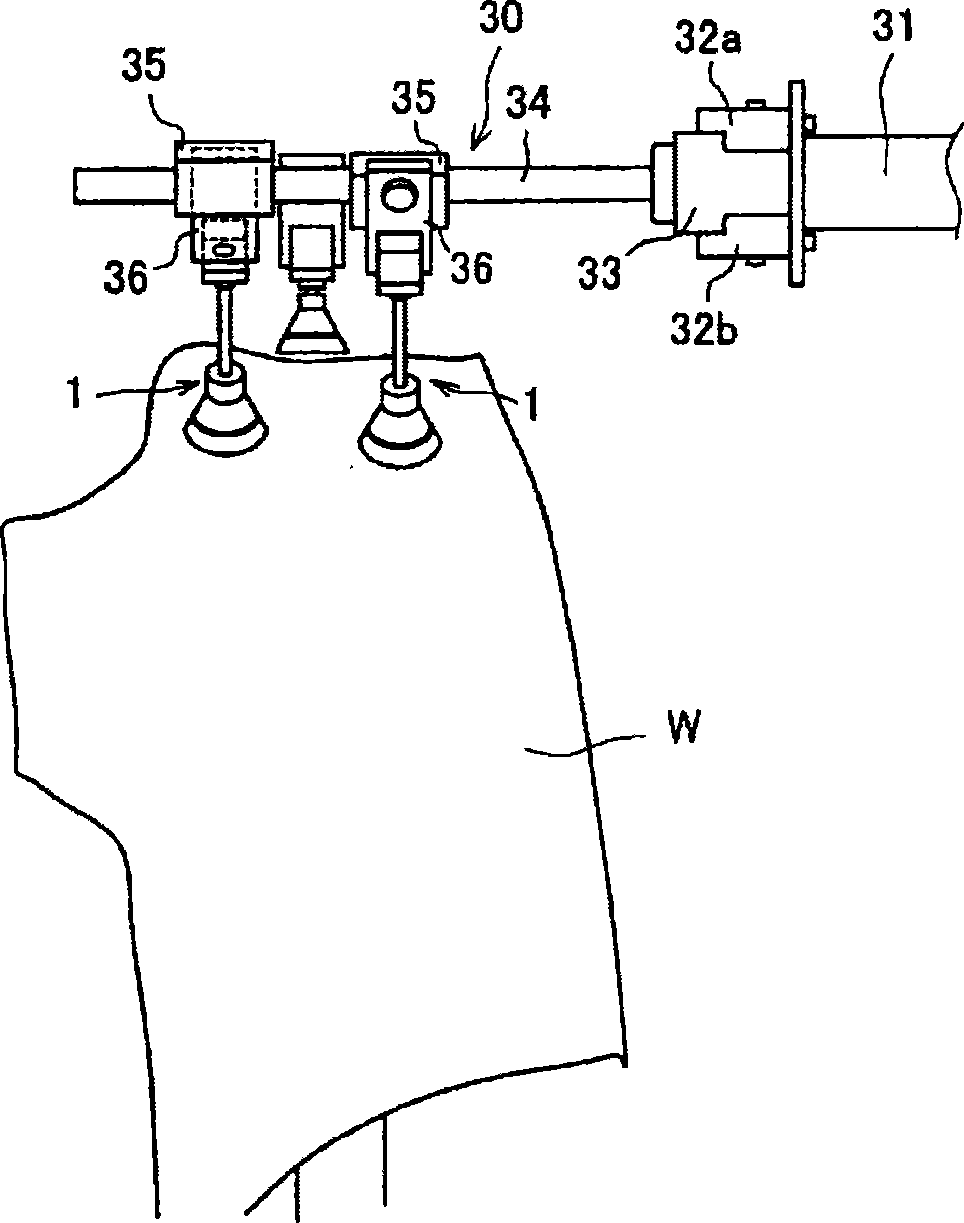
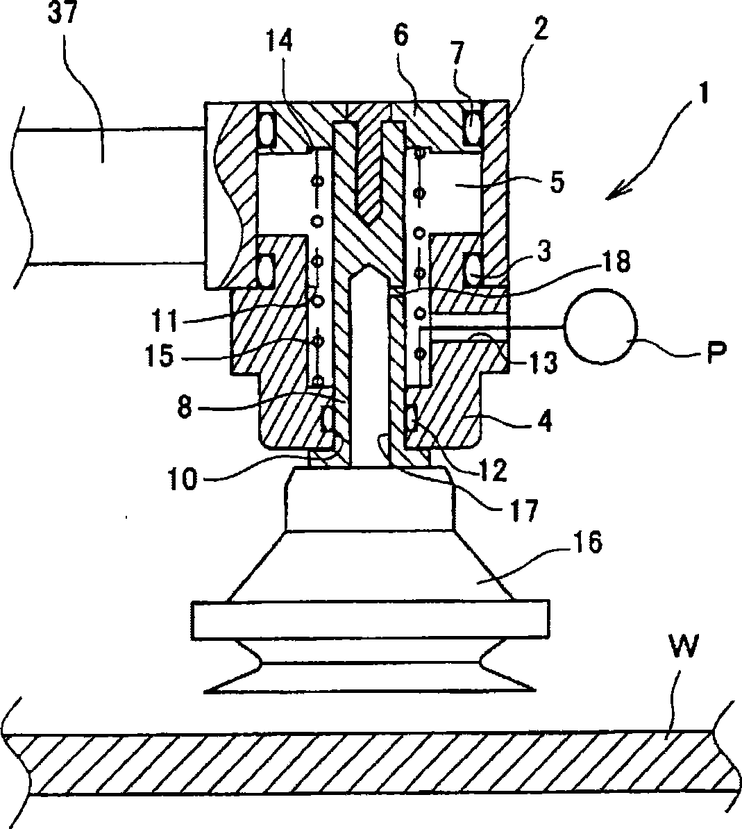
[0018] here, figure 1 is the front view of the transfer device applicable to the adsorption device of the present invention, figure 2 is the side view, image 3 is a partial sectional view showing the internal structure of the adsorption device, Figure 4 It is an explanatory diagram showing the adsorption state.

[0019] The suction device of the present invention can prevent scratches and the like from occurring on the surface of the workpiece even when it sucks and holds the curved portion or the inclined portion of the workpiece, and can hold it reliably. Banpa) W transfer device.

[0020] that is, figure 1 , figure 2 As shown, the bumper W transfer device 30 includes: two upper and lower holding plates 32a, 32b that are arranged at the front end of the robot arm 31 and extend in a direction perpendicular to the extending direction of the arm 31 at the front end of the ...


PUM


Abstract

To surely hold a work by preventing generation of scratches or the like on the surface of the work, even in the case of holding by suction the work having a curbed portion, an inclined portion and the like. [MEANS FOR SOLVING PROBLEMS] A supporting member (4) is arranged below a cylindrical section (2) wherein a piston member (6) is mounted, a small diameter hole (10) and a large diameter hole (11) for inserting a piston rod (8) is arranged on the supporting member (4), and a vacuum cup (16) is mounted on the leading end of the piston rod (8). A first suction hole (13) is made from the side surface of the supporting member (4) toward the large diameter hole (11), a third suction hole (17) is opened in the vacuum cup (16), at the center portion of the piston rod (8), and a second suction hole (18) is arranged for permitting the large hole (11) to communicate with the third suction hole (17). The communication area of the second suction hole (18) communicating with the third suction hole (17) is made smaller than the communication area of the large diameter hole (11) communicating with a piston chamber (5).

Description

technical field [0001] The present invention relates to a suction technique suitable for a device for transferring curved resin molded products such as bumpers of automobile parts, for example. Background technique [0002] Conventionally, when using a transfer device to transfer curved resin molded products such as bumpers of automobile parts, the workpiece is held by the suction device and transferred. At this time, even if the shape of the workpiece is different, one The following technology is known to deal with the device: the suction rod equipped with the suction buffer disk can be fixed at any position by the lock cylinder, and the technology of using a variable shape accessory that can change the direction of the suction buffer disk (for example, refer to the patent document 1), and in order to hold a workpiece whose wall thickness varies without deformation, a technique of freely changing the angle of the suction buffer plate by using a rotary joint (for example, re...

Claims


Application Information

Patent Timeline
Patent Type & Authority Applications(China)
IPC IPC(8): B25J15/06B65G47/91
CPCB25J15/0052B65G47/91B25J15/0616B25J15/0061
Inventor 胜谷宜生
Owner HONDA MOTOR CO LTD
Why Eureka
Try Eureka