Laminated glazing

A window glass, interlayer technology, applied in the direction of coatings, glass/slag layered products, layered products, etc.

Inactive Publication Date: 2009-06-10
PILKINGTON GROUP LTD
View PDF1 Cites 15 Cited by
  • Summary
  • Abstract
  • Description
  • Claims
  • Application Information

AI Technical Summary

Problems solved by technology

However, there still seems to be a problem with temperature sensitivity

Method used


Image

  • Laminated glazing
  • Laminated glazing
  • Laminated glazing

Examples


Embodiment Construction

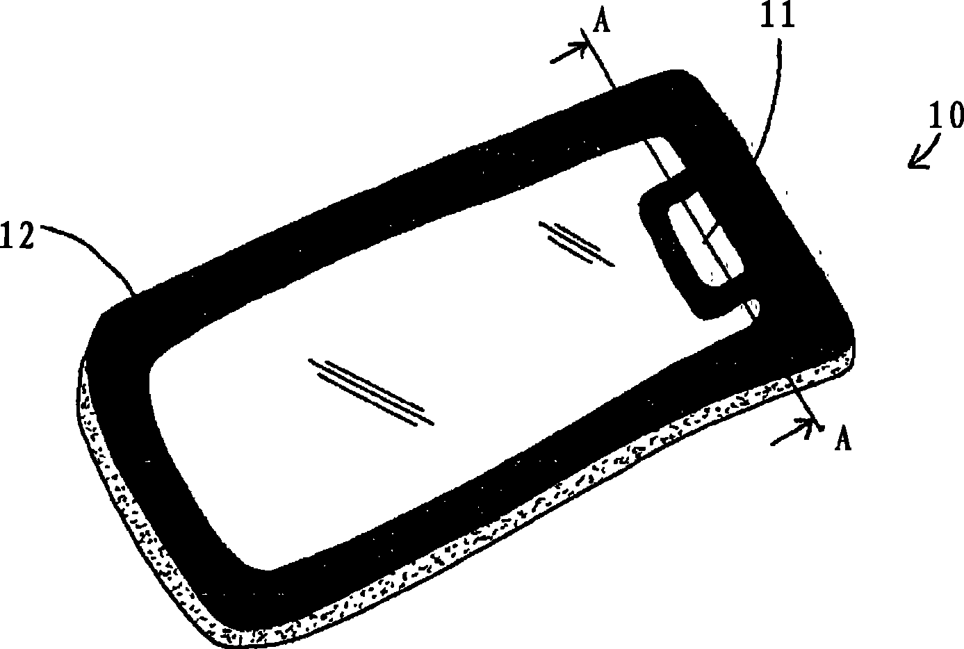
[0029] figure 1 A laminated glazing in the form of a sunroof 10 is shown containing electrical devices in the form of electroluminescent lamps 11 mounted within the sandwich construction. The electroluminescent lamp 11 is shown as being located near one edge of the window 10, however it could be located anywhere within the window such as in the center. Alternatively, two or more such electroluminescent lamps 11 may be provided. Near the perimeter of the sunroof 10 there is a dark strip 12 which is here to conceal and protect the sealant (not shown) used to secure the window into the vehicle (not shown) and also to conceal the power supply to the lights 11 Electrical connectors (bus bars, etc.). The shadow band 12 is made from an opaque ink that is screen printed on the window pane and subsequently fired. However, it could be constructed and applied in any other known way, or it is not required at all here.

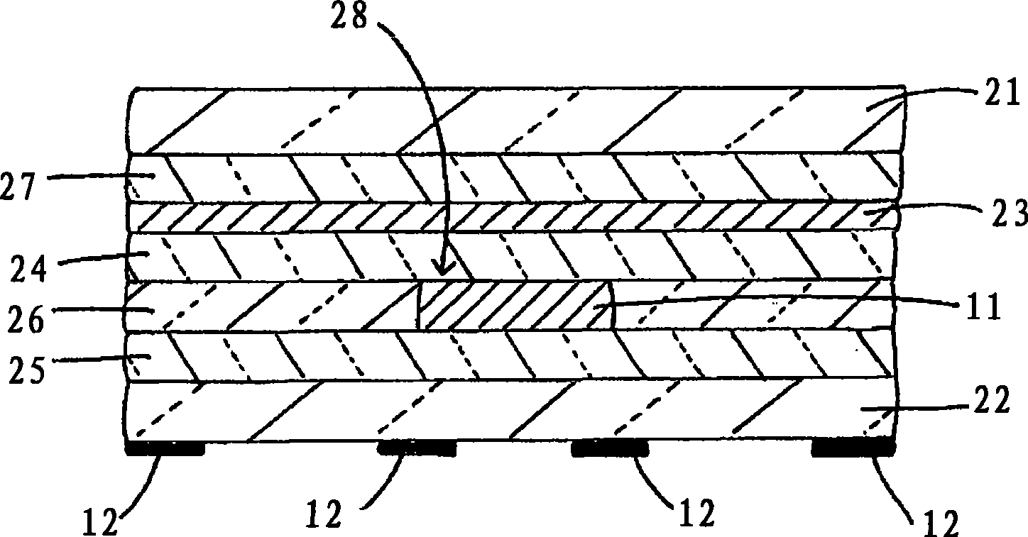
[0030] figure 2Further details are provided regarding the const...


PUM

PropertyMeasurementUnit
thicknessaaaaaaaaaa
thicknessaaaaaaaaaa
transmittivityaaaaaaaaaa

Abstract

A laminated glazing comprising two panes of glazing material joined together by at least one ply o f interlayer material, an electrical device (e.g. an electroluminescent lamp, an LCD or an SPD) located between the panes of glazing material and an infrared radiation reflecting means (e.g. reflective film) also located between the panes for reducing the amount of infrared radiation that may otherwise be incident upon the electrical device. One or more of the panes of glazing material and/or the at least one ply of interlayer material may be body-tinted. The glazing may be used as an automotivewindow, especially as a roof window.

Description

technical field [0001] The present invention relates to laminated glazings, and in particular to laminated glazings for use as automotive windows, for example as windshields, rear windshields, side windows or sunroofs in vehicles. Background technique [0002] It is known to provide motor vehicles with electrical devices (i.e. devices requiring electrical energy to carry out their functions), in particular devices capable of providing light-emitting functions (such as gated cabin lighting or ambient lighting) to the interior of a vehicle into which windows may be fitted window. An example of such a window is provided in WO 02 / 098179. It discloses laminated glass panels useful as skylights and comprising multiple layers of electroluminescent elements within a stack. When a voltage is applied to the light-emitting element, it emits light through at least one surface of the glass plate. [0003] Laminated glazing incorporating electrical devices, particularly in the form of ...

Claims


Application Information

Patent Timeline
Patent Type & Authority Applications(China)
IPC IPC(8): B32B17/10C03C27/12B60Q3/02
CPCB32B17/10174B32B17/10B32B17/10651B32B17/10036B60Q3/0213B32B17/10532B32B17/10339B32B17/10761E06B9/24B32B17/10055B32B17/10788B32B2367/00B32B17/1011B32B17/10504B32B17/10541B60Q3/208B32B17/10005C03C27/10
Inventor S·R·戴N·巴顿
Owner PILKINGTON GROUP LTD
Why Eureka
Try Eureka