Projection type display apparatus

一种显示装置、图像显示的技术,应用在放映装置、静态指示器、彩色电视等方向,能够解决效率降低、投射图像亮度降低等问题

Active Publication Date: 2009-06-10
PANASONIC CORP
View PDF1 Cites 6 Cited by
  • Summary
  • Abstract
  • Description
  • Claims
  • Application Information

AI Technical Summary

Problems solved by technology

Therefore, at the initial stage of life when the arc length is short, an unnecessary size of the black display area is set, and the efficiency is lowered, and the brightness of the projected image is lowered.

Method used


Image

  • Projection type display apparatus
  • Projection type display apparatus
  • Projection type display apparatus

Examples


Embodiment approach 1

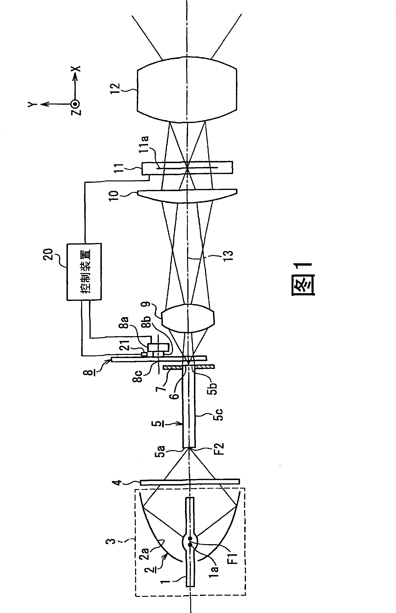
[0067] FIG. 1 is a front view showing the configuration of a projection display device according to Embodiment 1 of the present invention. Here, if xyz rectangular coordinates are defined as shown in the figure, FIG. 1 shows the structure with respect to the x-z plane.

[0068] In Fig. 1, 3 is a light source that emits white light, 5 is a glass rod that forms an optical unit as a light-emitting surface, 8 is a rotary color filter, 9 is a relay lens as an illumination optical unit, and 11 is a spatial light modulation A transmissive liquid crystal panel of the element, 12 is a projection lens.

[0069] The light source 3 is composed of a discharge lamp 1 and an elliptical mirror 2 . As the discharge lamp 1, an ultra-high pressure mercury lamp can be used. Since the ultra-high pressure mercury lamp emits white light, has high brightness, and has good light-gathering performance, it can efficiently gather light through the elliptical mirror 2 .

[0070] The elliptical mirror 2...

Embodiment approach 2

[0108] 6A is a side view showing the configuration of a projection display device according to Embodiment 2 of the present invention. The same reference numerals are assigned to the same units as those of the device according to Embodiment 1 shown in FIG. 1 , and overlapping descriptions will be omitted.

[0109] The projection display device of this embodiment is different from the embodiment shown in FIG. The device of 1 is the same.

[0110] The reflective film 61 is a multilayer film provided on the incident end surface of the rod integrator 5 . Figure 6B The enlarged view of is a schematic view when the incident end face of the rod integrator 5 is viewed from the direction of the optical axis 13 . The reflective film 61 is provided except for the opening 64 .

[0111] The light collected by the elliptical mirror 2 passes through the opening 64 and reaches the output end surface 5 b of the rod integrator 5 . The light emitted from the emission end surface 5 b enters t...


PUM


Abstract

A projection type display apparatus comprises a rotational color filter (8) having color filters (8R, 8G, 8B) that transmit a white light to a specific color light emitted from a light emitting surface (6), a spatial light modulation element (11) disposed substantially in a conjugate relationship with the light emitting surface and modulating the incident light from the rotational color filter to perform an image display, and a controller (20) performing control so that the rotation of the rotational color filter is synchronized with the image display performed by the spatial light modulation element. In synchronization with passing of the borderlines (51, 52, 53), which are between the filters of each color of the rotational color filter, across each of partial light emitting regions (6a, 6b, 6c, ...) set by dividing the light emitting surface, the controller switches between the normal image display and the OFF-state in which light is blocked, for each of the partial display regions (14, 15, 16, ...) of the spatial light modulation element corresponding to each of the partial light emitting regions. The use efficiency of illumination light by the spatial light modulation element is increased, so that the color brightness of a projected image can be enhanced while sufficiently maintaining the effect of preventing the color mixture caused by adjacent color filters.

Description

technical field [0001] The present invention relates to a projection display device for projecting a large-screen image onto a screen by using a spatial light modulation element and a projection lens to form an optical image by being illuminated by light emitted from a light source and obtaining an image signal from the outside. Background technique [0002] Conventionally, projection display devices using various spatial light modulators are known as video equipment for large screens. They use, for example, a transmissive or reflective liquid crystal panel as a spatial light modulation element, illuminate the liquid crystal panel with a light source, form an optical image based on an externally supplied video signal on the liquid crystal panel, and magnify the optical image with a projection lens. projected on the screen. [0003] In recent years, the demand for higher luminance has been increasing, and three-panel projection display devices using spatial light modulation ...

Claims


Application Information

Patent Timeline
Patent Type & Authority Applications(China)
IPC IPC(8): G03B21/14G02B26/00G02B26/08G02B27/18G02F1/13G02F1/1335G02F1/13357G03B21/00
CPCG09G2310/0235G09G2310/024G02F2203/12G03B21/14H04N9/3117G09G3/342G09G3/3611H04N9/3197G09G3/2014G02B26/008G03B21/005G03B21/2053G03B33/08
Inventor 和田充弘三户真也伏见吉正
Owner PANASONIC CORP
Why Eureka
Try Eureka