Horizontal lathe center frame
A horizontal lathe and center frame technology, applied in the direction of large fixed members, metal processing machinery parts, metal processing equipment, etc., can solve problems that affect production, small space, and unsatisfactory use effects
- Summary
- Abstract
- Description
- Claims
- Application Information
AI Technical Summary
Problems solved by technology
Method used
Image
Examples
Embodiment Construction
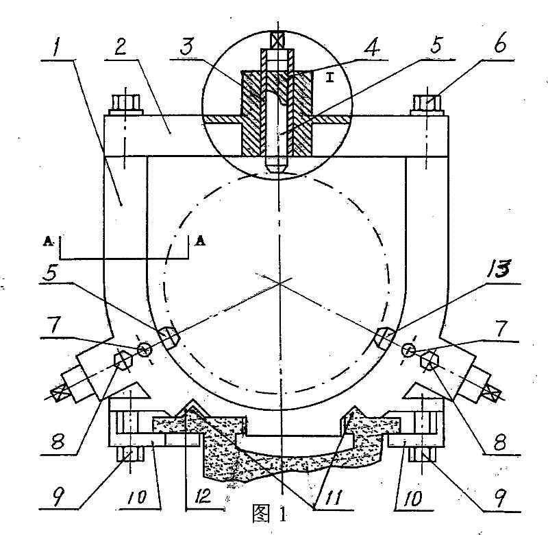
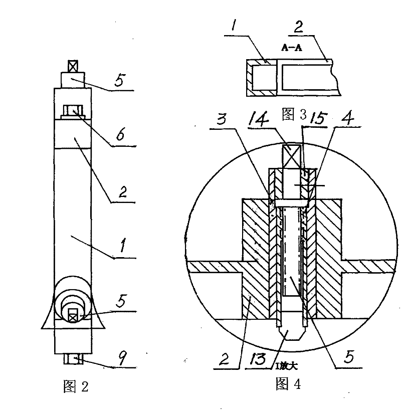
[0012] As shown in Figures 1-4, a horizontal lathe center frame includes an upper frame body 2, a lower frame body 1, a fixing bolt 6, a pressure plate bolt 9 and a pressure plate 10, wherein the fixing bolt 6 connects the The upper frame body 2 and the lower frame body 1, the lower frame body 1 is a U-shaped frame, and an equilateral triangle is formed with the center of the inscribed circle of the U-shaped frame as the center, and the two vertices of the equilateral triangle are located at the bottom of the lower frame body 1. On both sides, the other vertex is located in the middle of the upper frame body 2, and a frame body adjusting mechanism is respectively provided at the three vertexes of the equilateral triangle, which is characterized in that: the frame body adjusting mechanism is composed of a sliding sleeve 3, a sliding block 13 , frame claw 4, adjusting screw 5, adjusting screw handle 14, retaining ring 15, frame claw locking bolt 7 and sliding sleeve locking bolt ...
PUM
 Abstract
Description
Claims
Application Information
 - R&D
- Intellectual Property
- Life Sciences
- Materials
- Tech Scout
- Unparalleled Data Quality
- Higher Quality Content
- 60% Fewer Hallucinations
Browse by: Latest US Patents, China's latest patents, Technical Efficacy Thesaurus, Application Domain, Technology Topic, Popular Technical Reports.
© 2025 PatSnap. All rights reserved.Legal|Privacy policy|Modern Slavery Act Transparency Statement|Sitemap|About US| Contact US: help@patsnap.com


