
Numerical control main axle unit

A CNC spindle and spindle technology, which is applied to metal processing mechanical parts, driving devices, metal processing equipment, etc., can solve the problems of difficult control of spindle machining accuracy and difficult disassembly of the spindle, so as to achieve easier control of machining accuracy, improve accuracy, and smoothness. high effect

Inactive Publication Date: 2009-06-17
洪清德
View PDF2 Cites 10 Cited by
  • Summary
  • Abstract
  • Description
  • Claims
  • Application Information

AI Technical Summary

Problems solved by technology

[0004] The main purpose of the present invention is to overcome the disadvantages that the machining accuracy of the main shaft is not easy to control and the main shaft is not easy to disassemble in the prior art mechanical processing, and to provide a numerically controlled main shaft unit

Method used


Image

  • Numerical control main axle unit

Examples


Embodiment Construction

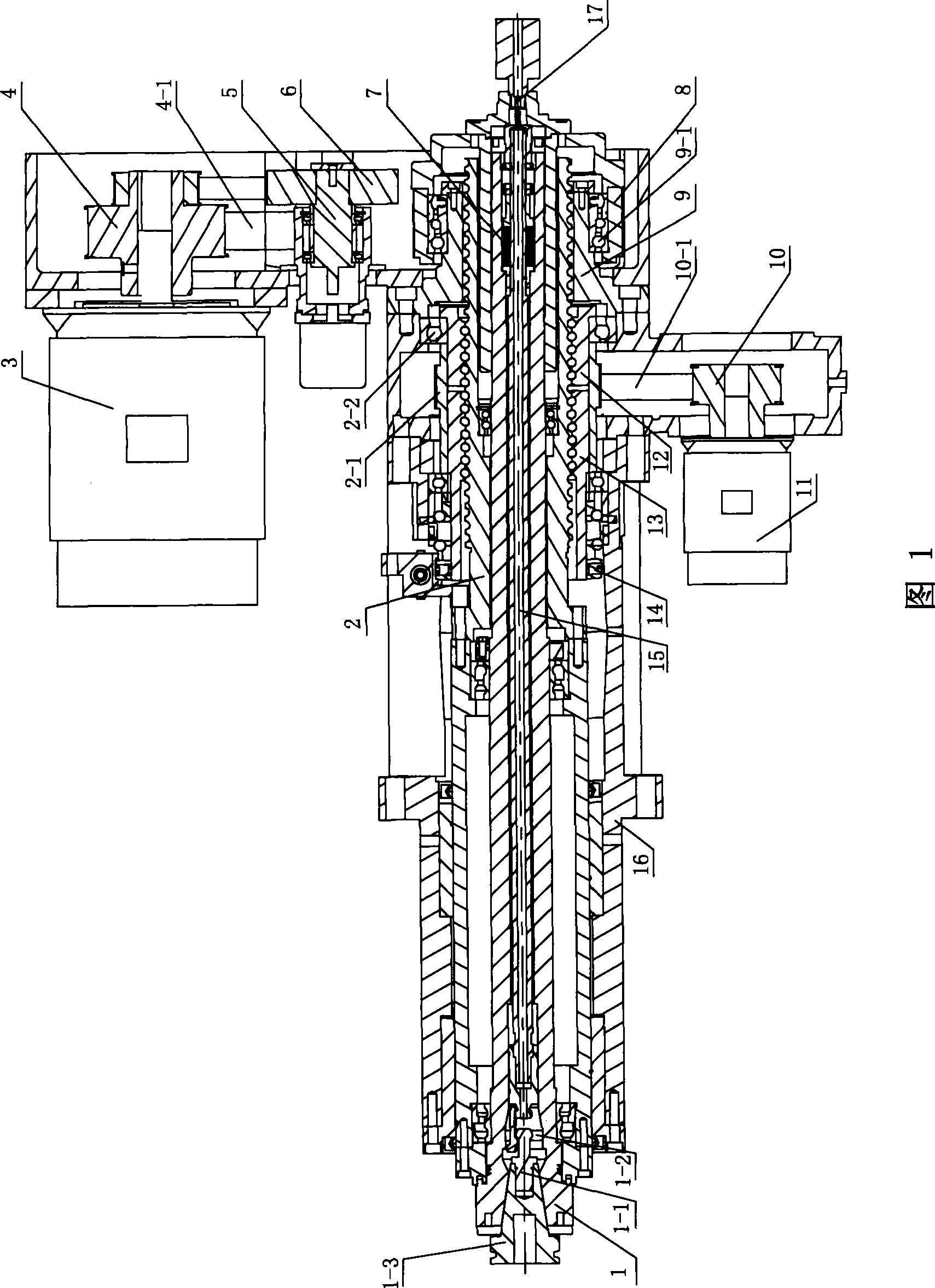
[0021] With reference to Fig. 1, a kind of numerical control spindle unit of the present invention comprises:

[0022] A main shaft 1 for carrying machining tools, the main shaft 1 has an inner cavity through its two ends;

[0023] A hollow tie rod 15 is installed in the inner cavity of the main shaft 1, and its front end is connected with a pulling claw 1-2, and the pulling claw 1-2 is detachably connected with a tension screw 1-1, and the tension screw 1- 1 detachably connect a machining tool 1-3, the machining tool 1-3 can be a tool for cutting, drilling, boring, reaming, tapping and other functions; the pull claw 1-2 and the tension screw 1-1 The connection mode between them is clamping connection, and the connection mode between the tensioning screw 1-1 and the machining tool 1-3 is threaded connection;

[0024] A main shaft feed driving device for driving the axial sliding of the main shaft 1 includes a first servo motor 11 connected to the numerical control center of t...


PUM


Abstract

The invention relates to the field of a machining main shaft unit, in particular to a numerical control main shaft unit, which comprises a main shaft for bearing a machining tool, a hollow pull rod, a main shaft feed driving device for driving the main shaft to slide axially, a main shaft rotation driving device for driving the main shaft to rotate radially, and a box body. Compared with the prior art, the numerical control main shaft unit is mainly arranged on a machining device to perform machining operations of drilling, reaming, boring, tapping, and the like, the feeding speed of the main shaft is easy to control, the vibration is smaller when the machining is in place, the precision of the axial dimension in the process of machining a workpiece is easy to control, the surface finish quality of a machined workpiece is high, and wearing parts are easy to replace, thus the numerical control main shaft unit sufficiently meets the requirements of the modern machining.

Description

technical field [0001] The invention relates to the field of machining spindle units, in particular to a numerically controlled spindle unit. Background technique [0002] The spindle unit is mainly installed on mechanical processing equipment for drilling, reaming, boring, tapping and other mechanical processing. The traditional driving method is pneumatic or hydraulic drive, and the processing position limit method is mechanical limit. This kind of driving mode is single, which is prone to defects such as air leakage or oil leakage, the feed speed is not easy to control, the vibration is large when the machining is in place, the axial dimension accuracy is not easy to control when machining the workpiece, the surface finish of the processed workpiece is not high, and the wearing parts are not easy to replace . With the continuous development of the machinery industry, this traditional spindle unit can no longer meet the needs of the market. [0003] Although the CNC spin...

Claims


Application Information

Patent Timeline
Patent Type & Authority Applications(China)
IPC IPC(8): B23Q5/10B23B19/00
Inventor 洪清德
Owner 洪清德
Learn More