Spark identification tool-setting method and abrasive machining automatic system

An automation system and grinding technology, applied in metal processing equipment, parts of grinding machine tools, grinding/polishing equipment, etc.

Active Publication Date: 2009-06-17
QIQIHAR HUAGONG MACHINE +1
View PDF0 Cites 49 Cited by
  • Summary
  • Abstract
  • Description
  • Claims
  • Application Information

AI Technical Summary

Problems solved by technology

In the subsequent processing process, the visual technology is also used to solve the problem of online automatic measurement of the workpiece size, and combined with the multi-axis control system to automatically complete the entire grinding process

Method used


Image

  • Spark identification tool-setting method and abrasive machining automatic system
  • Spark identification tool-setting method and abrasive machining automatic system
  • Spark identification tool-setting method and abrasive machining automatic system

Examples


Embodiment Construction

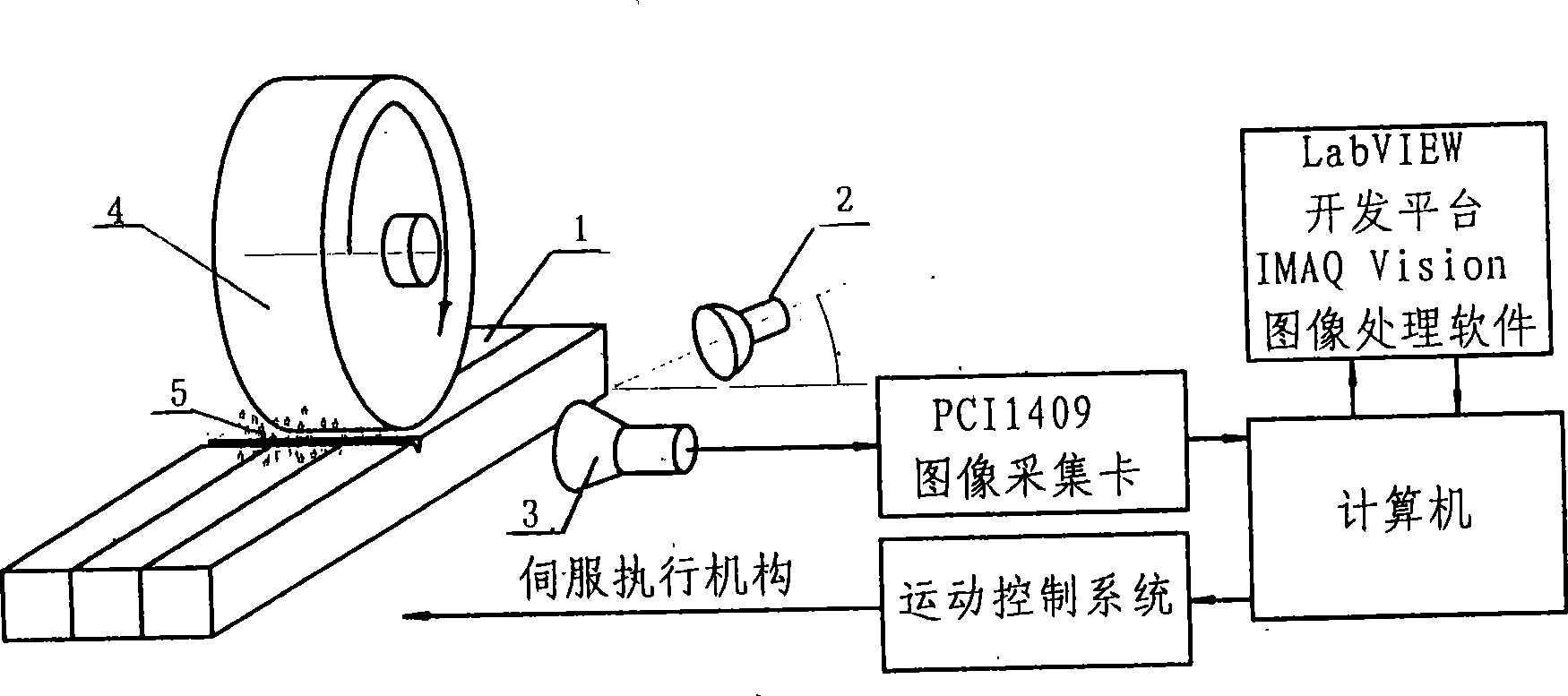
[0018] The overall structure of the visual tool setting and grinding control system is shown in Figure 1. During tool setting, the motion control system drives the grinding wheel to approach the grinding surface with an appropriate motion program, and the visual spark monitoring system starts at the right time. When the grinding wheel contacts the processing surface and generates tiny sparks, the sensitive visual system will immediately detect this information , send a command to the motion control system to stop feeding, and end the tool setting process. Since the information for judging the tool setting situation is the friction spark, the whole tool setting process has nothing to do with the actual size of the grinding wheel and the feeding stroke, thus completely avoiding the problem of grinding wheel wear compensation. At the end of the tool setting, the base point (zero point) of the grinding motion control is determined, and the motion control system immediately enters ...


PUM


Abstract

The invention discloses a method for setting a tool through sparkle identification and an automatic system for grinding processing. The method and the system achieve the intelligent automatic control for the whole grinding process and accurately and reliably solve the problem of automatic tool setting, the problem of dimension compensation caused by the abrasion of a grinding wheel, and the problems of on-line dimension measurement and motion servo control in the grinding process. The method organically combines a vision technique, a PLC technique and a motion control technique, and provides a solution for solving the problems of tool setting, on-line dimension measurement and grinding wheel wear compensation by using the vision technique, and the problem of motion servo control by using the PLC technique and the motion control technique. The method makes use of the vision technique to automatically identify the operating condition contacted with a workpiece, and switch the operating condition to a grinding processing state instantly so as to solve the problem of automatic tool setting, thus the method can combine a plurality of mature correlation techniques to construct the automatic system which integrates detection and motion control. The method and the automatic system achieve the accurately automatic tool setting, solve the problems of the wear measurement and compensation of the grinding wheel, and open up a novel approach for fully automatic and intelligent control in the grinding process.

Description

(1) Technical field [0001] The invention belongs to the intelligent automation device of metal grinding processing technology (2) Background technology [0002] Modern manufacturing technology is developing towards flexible manufacturing (FMS), computer integrated manufacturing (CIM) and intelligent manufacturing (IM). Among them, intelligent manufacturing (IM), as an important content of advanced manufacturing technology, has increasingly become a research hotspot. It aims to introduce the theory and method of intelligent control into the manufacturing process. By simulating the thinking and reasoning activities of human experts, it replaces and extends part of the brain power in the manufacturing environment, so that the manufacturing system can automatically detect its operating status and environmental changes. When receiving external and internal incentives, it can make correct judgments and decisions to ensure that the system obtains a robust processing effect. [00...

Claims


Application Information

Patent Timeline
Patent Type & Authority Applications(China)
IPC IPC(8): B24B49/12
Inventor 王长利周立富周立民刘祥峰黄俊范壮林寅彬
Owner QIQIHAR HUAGONG MACHINE
Why Eureka
Try Eureka