Passive paddle changing wind power generator

A wind-driven generator, passive technology, applied in the direction of wind-driven engine, wind-driven motor combination, wind-driven engine control, etc., can solve problems such as high manufacturing cost, complex structure, wind-driven generator influence, etc., to improve safety and stability, The effect of pitch change is obvious and the structure is simple

Inactive Publication Date: 2009-06-17
ZHEJIANG HUAYING WIND POWER GENERATOR
View PDF4 Cites 8 Cited by
  • Summary
  • Abstract
  • Description
  • Claims
  • Application Information

AI Technical Summary

Problems solved by technology

However, due to the current mechanically controlled pitch device, the structure is relatively complicated, the transmission performance is unstable, and the ma...

Method used


Image

  • Passive paddle changing wind power generator
  • Passive paddle changing wind power generator
  • Passive paddle changing wind power generator

Examples


Embodiment 1

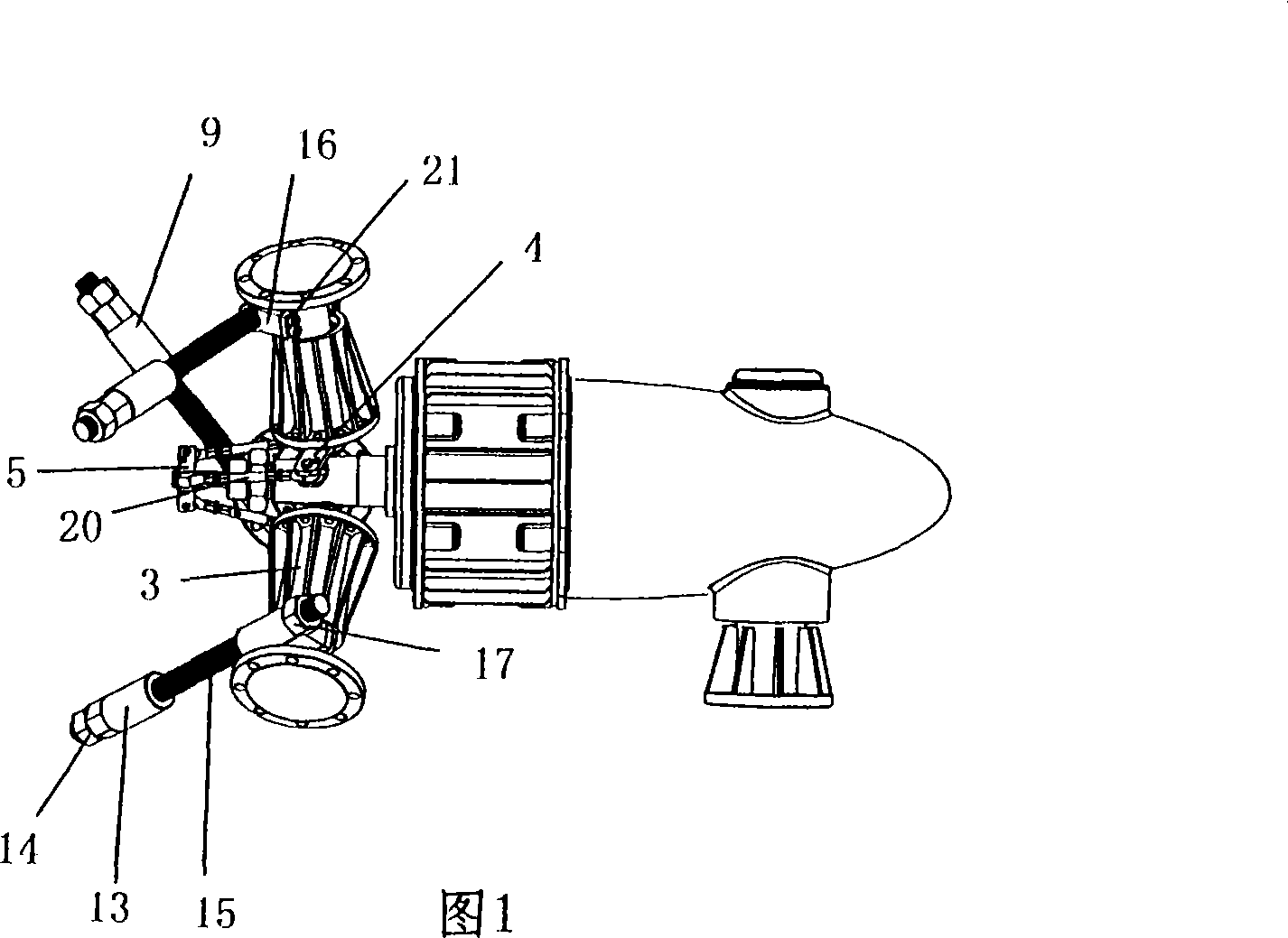
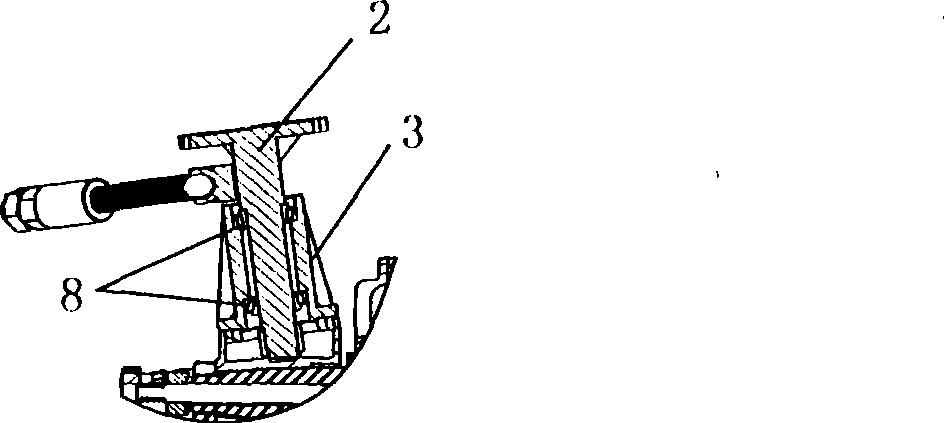
[0015] As shown in Figures 1 and 2, the passive pitch wind turbine described in this embodiment includes a fan blade 1, a blade connecting handle 2, a hub spoke tube 3, a crank 4, a synchronous disc 5, a motor shaft 6, a tie rod 7. The fan blade 1 is installed on the fan blade connecting handle 2, and the fan blade connecting handle 2 is connected with the hub spoke tube 3 through the bearing 8, and can rotate relatively. The root of the fan blade connecting handle 2 is connected with the crank 4 by a key, and the crank 4 is connected with the synchronizing plate 5 through the linkage structure composed of three connecting rods 20 and six joint bearings, so that the rotary motion of the fan connecting handle 2 is converted into synchronization. Reciprocating movement of the disc 5. The synchronizing plate 5 is matched with the pull rod 7 passing through the hollow motor shaft 6 by a flat key, and the pull rod 7 is provided with bolts to fix the pull rod 7 and the synchronizing...

Embodiment 2

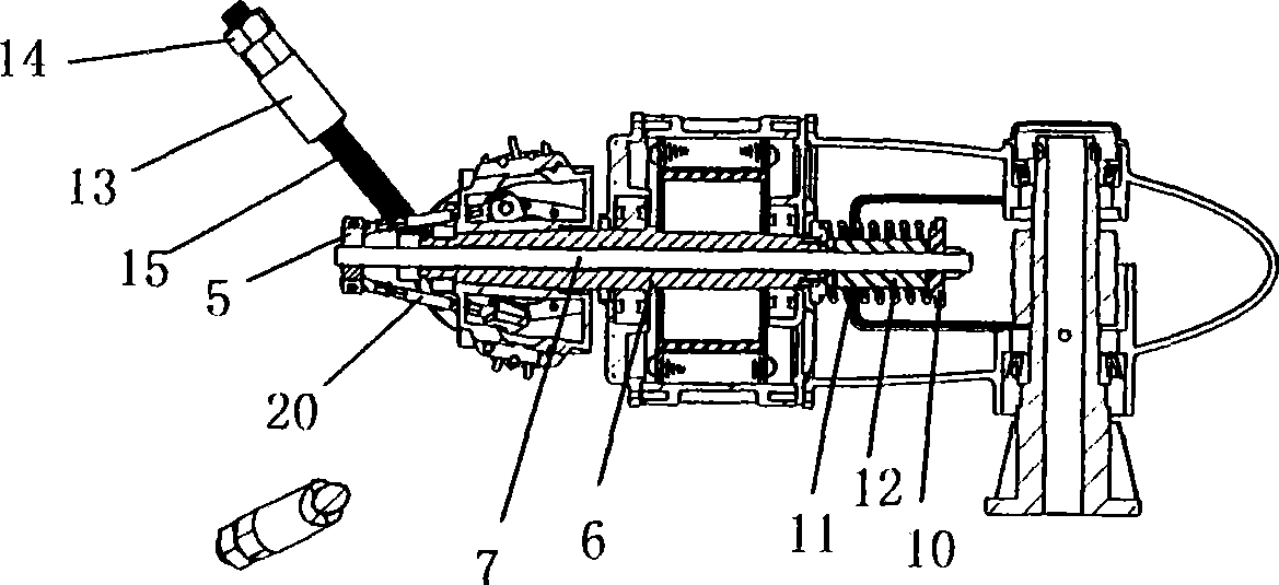
[0017] like image 3 As shown, the passive pitch wind turbine described in this embodiment is based on Embodiment 1, and a spring cover 10 is provided at one end of the pull rod 7, and a spring 11 is provided between the motor shaft 6 and the spring cover 10. , the spring 11 is provided with a damper 12, and the elastic force generated by the deformation of the spring 11 forms a pair of balance forces through the centrifugal force of the pull rod 7, the concentric disc 5, the crank 4, the blade connecting handle 2 and the centrifugal hammer 9. When the rotation speed of the blade 1 is slowed down and the centrifugal force of the centrifugal hammer 9 is reduced, the angle of the fan blade 1 is automatically reset by the elastic force of the spring 11, and the compression and reset of the spring 11 are restricted by the damper 12, which can eliminate the frequent change of the wind speed. The vibration caused by the pitch, so as to achieve the purpose of more stable passive pitc...


PUM


Abstract

The invention relates to a passive variable propellers aerogenerator, comprising fan blades, fan blade connection handles, hub radial canals, cranks, synchronous disks, a motor shaft and pull rods, wherein, the fan blades are installed on the fan blade connection handles connected with the hub radial canals by bearings, the fan blade connection handles and the hub radial canals can relatively rotate, the root parts of the fan blade connection handles are connected with a crank connected with the synchronous disks by linkage structures, the pull rods are connected on the synchronous disks, and centrifugal hammers are installed on the fan blade connection handles. In the aerogenerator, the variable propellers have simple structure, favorable stability and obvious effect, control and adjust the angle of each wind wheel blade handle by the centrifugal force to the centrifugal hammers by the rotation of the aerogenerator, and cause the wind wheel of the aerogenerator to be at an optimal start angle during low wind and to be at an optimal windward angle position at rated wind speed; during strong wind force, the rotate speed of the aerogenerator can be controlled with a rated rotate speed, thereby preventing the overload of the aerogenerator and improving the safety and the stability of the aerogenerator.

Description

technical field [0001] The patent of the present invention relates to a wind generator, especially a passive pitch wind generator. Background technique [0002] In today's society, non-renewable energy is decreasing day by day, and energy problems are becoming more and more serious. As an inexhaustible, green and environmentally friendly renewable energy, wind energy has a good development prospect and is the main direction of my country's current implementation and utilization of new energy and renewable energy. In wind power generation, due to the change of wind speed in nature, in order to obtain the maximum wind energy and achieve the maximum utilization effect, the pitch technology is often used to adjust the angle between the wind blade and the windward surface to the best state. Due to its advantages of low wind start and high wind speed limit, this technology improves the working performance of wind turbines in various weather conditions, so it is more and more widel...

Claims


Application Information

Patent Timeline
IPC IPC(8): F03D9/00F03D1/06F03D7/04F03D9/25
CPCY02E10/723Y02E10/721Y02E10/72
Inventor 郭峰杨晶明
Owner ZHEJIANG HUAYING WIND POWER GENERATOR
Why Eureka
Try Eureka