Supercharge Your Innovation With Domain-Expert AI Agents!

Stopping caliper

A caliper and parking technology, applied in the direction of brake actuators, axial brakes, brake types, etc., can solve the problems of unstable braking torque, tight installation space and occupation of parking devices, and achieve stable braking torque , simple structure and high reliability

Inactive Publication Date: 2011-02-16
CHERY AUTOMOBILE CO LTD
View PDF0 Cites 0 Cited by
  • Summary
  • Abstract
  • Description
  • Claims
  • Application Information

AI Technical Summary

Problems solved by technology

[0002] The main forms of automobile parking devices in the prior art are drum-type parking brakes and dribbling drum-type parking brakes. There are some difficult defects in the above-mentioned two kinds of parking devices. The torque is unstable, and the theoretical calculation is difficult, and the input force-output force is basically determined according to the test; for the belt drum brake, because many components such as the brake shoe, pull arm and return spring inside the drum brake occupy a large The space makes it very difficult to arrange the dribbling drum brake. In the current situation where the third-generation hub bearings are increasingly used in automobiles, the installation space of the parking device is even more tight.

Method used


Image

  • Stopping caliper
  • Stopping caliper
  • Stopping caliper

Examples


Embodiment approach

[0023] 1) Parking process

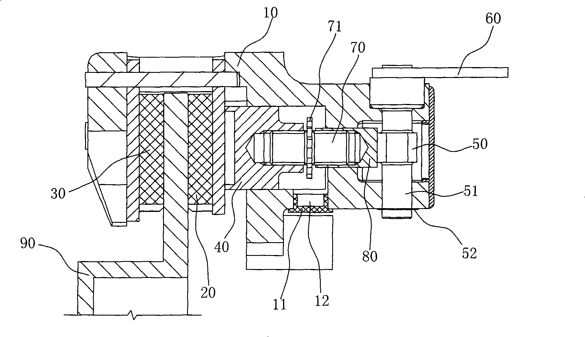
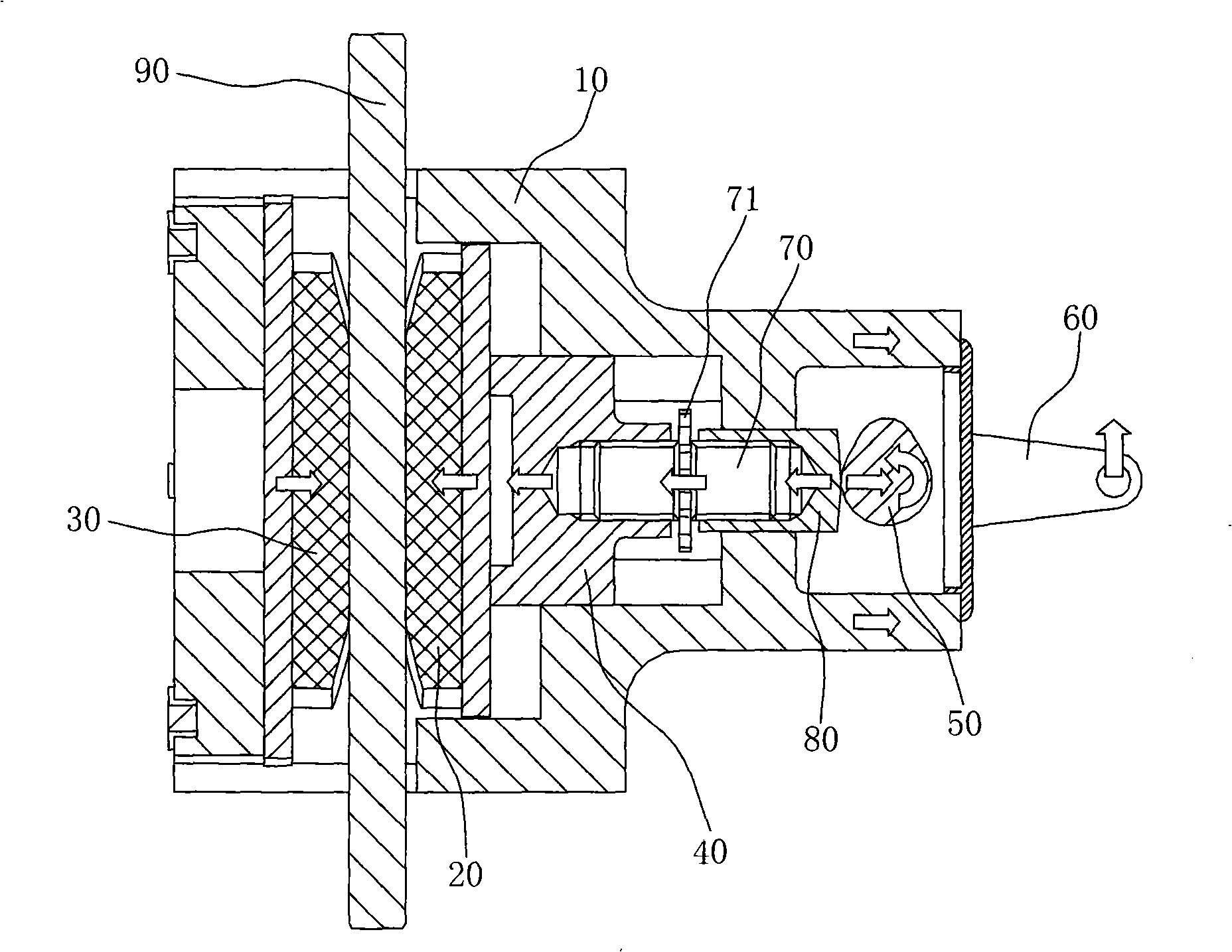
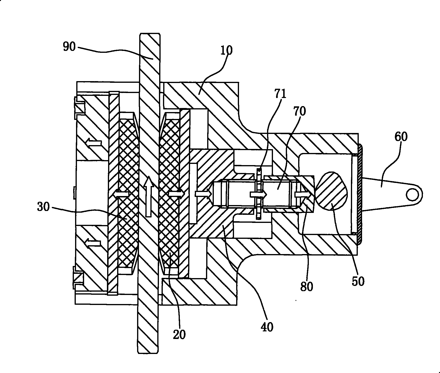
[0024] After the vehicle stops, the driver pulls the parking handle, and the power is transmitted to the parking pull arm 60 through a transmission mechanism such as a parking cable, such as figure 2 As shown by the arrow in the figure, the parking pull arm 60 will drive the camshaft 51 to rotate, and the camshaft 51 will drive the cam 50 to rotate accordingly. When the cam 50 rotates, it will drive the sheath 80 to move to the side of the piston 40, and the sheath 80 will then push The adjusting stud 70 moves to the side of the piston 40, and the adjusting stud 70 pushes the piston 40 to move to the side of the brake disc 90, and the piston 40 moves along the direction defined by the cavity in the caliper body 10, and pushes the movable brake block 20 Attached to the inner working surface of the brake disc 90; at the same time, when the cam 50 drives the sheath 80, the sheath 80 gives a reaction force to the cam 50, and this reaction force will ma...


PUM


Abstract

The invention belongs to the technical field of vehicle brake parking, in particular to a parking clamp. The invention comprises a movable brake block and a fixed brake block arranged on a clamp body; one end of the movable brake block is fixed on a piston; the piston is arranged in the concave cavity of the clamp body and can move along a direction limited by the concave cavity; the end of the piston far away from the movable brake block is provided with a cam transmission mechanism; the cam transmission mechanism is fixed on the clamp body, is driven to rotate by a draw arm, and pushes the piston to move along the direction limited by the concave cavity. According to the technical scheme, in the clamp, the drive mechanism of the movable brake block is set as the cam transmission mechanism, and a more ideal input-output relation can be obtained by using the controllability of a cam profile, thereby obtaining a more stable brake torque; moreover, the cam transmission mechanism has high reliability, fewer parts and simple structure, thus being suitable to be mounted in narrow and compact working environment in particular.

Description

technical field [0001] The invention belongs to the technical field of automobile braking and parking, and in particular relates to a parking caliper. Background technique [0002] The main forms of automobile parking devices in the prior art are drum-type parking brakes and dribbling drum-type parking brakes. There are some difficult defects in the above-mentioned two kinds of parking devices. The torque is unstable, and the theoretical calculation is difficult, and the input force-output force is basically determined according to the test; for the belt drum brake, because many components such as the brake shoe, pull arm and return spring inside the drum brake occupy a large The space makes it very difficult to arrange the dribbling drum brake. In the current situation that the third-generation hub bearings are increasingly used in automobiles, the installation space of the parking device is even more tight. Contents of the invention [0003] The object of the present in...

Claims


Application Information

Patent Timeline
Patent Type & Authority Patents(China)
IPC IPC(8): F16D55/02F16D65/20F16D65/18
Inventor 李成
Owner CHERY AUTOMOBILE CO LTD
Features
  • R&D
  • Intellectual Property
  • Life Sciences
  • Materials
  • Tech Scout
  • Unparalleled Data Quality
  • Higher Quality Content
  • 60% Fewer Hallucinations
Learn More