Backlight unit
A technology for a light source part and a light source, which is applied in the field of the backlight source part, can solve the problems of small improvement effect of uneven light incidence and enlarged area of uneven light incidence, etc.
- Summary
- Abstract
- Description
- Claims
- Application Information
AI Technical Summary
Problems solved by technology
Method used
Image
Examples
Embodiment 7
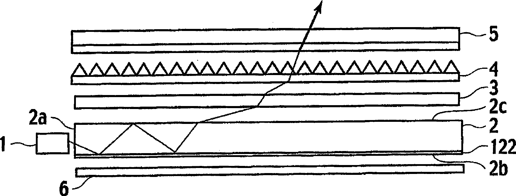
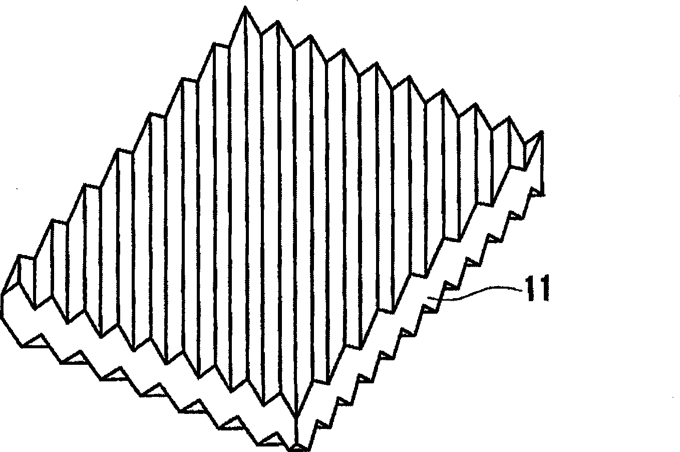
[0106]Embodiment 7 differs from Embodiment 6 in that the angle θ1 of the first prism row 42 is 15°, and the angles ψ1 and ψ2 of the third prism row 52 are both 45°. The other configurations are the same as in Embodiment 6. Embodiment 8 differs from Embodiment 7 in that the first prism array 42 is arranged perpendicular to the side surface 2 a. Comparative Example 3 is different from Example 7 in that the first prism array 42 is arranged at an inclination of approximately 20° from the side surface 2 a. In Examples 7 and 8, compared with Comparative Example 3, both the front luminance and the light incident unevenness are good. Furthermore, compared with Example 7, Example 8 has slightly better front brightness. In this way, it is desirable that the first prism array 42 is arranged parallel to or perpendicular to the side surface 2a. Furthermore, it is desirable that the first prism array 42 is arranged parallel to the side surface 2a.
[0107] In Examples 9 and 10 and Compar...
Embodiment 11
[0108] The angle θ1 of the first prism row 42 in Examples 11 and 12 and Comparative Example 6 is different from that of Example 7, and the other configurations are the same as those of Example 7. Compared with Example 7 in which the angle θ1 is 15°, Example 11 in which the angle θ1 is 20° has lower frontal luminance and the same light incident unevenness. In Example 12 where the angle θ1 is 10°, compared with Example 7, the front brightness is good, and the light incident unevenness increases. In Comparative Example 6 where the angle θ1 is 25°, compared with Examples 7, 11, and 12, although the frontal luminance is lowered, the unevenness of incident light is at the same level. Thus, it is desirable that the angle θ1 is in the range of 20° or less.
Embodiment 13
[0109] Embodiments 13 and 14 and Comparative Examples 7 and 8 differ from Embodiment 7 in the angle θ2 of the first prism row 42 , and the other configurations are the same as Embodiment 7. In Example 13 where the angle θ2 is 40°, compared with Example 7 where the angle θ2 is 48°, the front luminance is lowered, and the light incident unevenness is the same. In Example 14 where the angle θ2 is 55°, compared with Example 7, the front luminance is lowered, and the light incident unevenness is increased. Compared with Examples 7, 13, and 14 in Comparative Examples 7 and 8 where the angle θ2 is 35° and 60°, respectively, although the frontal brightness is lowered, the difference in incident light is at the same level. Thus, it is desirable that the angle θ2 is in the range of 40° to 55°.
PUM
| Property | Measurement | Unit |
|---|---|---|
| length | aaaaa | aaaaa |
| thickness | aaaaa | aaaaa |
| thickness | aaaaa | aaaaa |
Abstract
Description
Claims
Application Information
 - R&D
- Intellectual Property
- Life Sciences
- Materials
- Tech Scout
- Unparalleled Data Quality
- Higher Quality Content
- 60% Fewer Hallucinations
Browse by: Latest US Patents, China's latest patents, Technical Efficacy Thesaurus, Application Domain, Technology Topic, Popular Technical Reports.
© 2025 PatSnap. All rights reserved.Legal|Privacy policy|Modern Slavery Act Transparency Statement|Sitemap|About US| Contact US: help@patsnap.com


