Manufacturing process of differential gear

A manufacturing method and technology of a differential gear, which is applied in the field of differential gear manufacturing, can solve problems such as noise, differential gear shifting, high manufacturing costs, etc., and achieve the effects of reducing costs, improving quality, and reducing the number of parts

Inactive Publication Date: 2004-03-31
陈李烨
View PDF1 Cites 11 Cited by
  • Summary
  • Abstract
  • Description
  • Claims
  • Application Information

AI Technical Summary

Problems solved by technology

[0005] It can be seen from the structure of the driving wheel of the existing differential described above that the previous proposal needs to manufacture the driving wheel 1 by powder forming stamping, install the umbrella-shaped differential wheels 5 and 6 on both sides of the positioning shaft 7, and then place the positioning piece 3 Lock the driving wheel 1 with the screw 2 and fix it in the concave structure of the driving wheel 1. There are many parts and it is not easy to assemble and center; the latter case needs to be combined with the supporting body 61, its central hole 613, and the two wheels on both sides. The grooves 614, 614', the symmetrically arranged pin holes 615, 615', the outer gear ring 62 and the flange 621 with a roughly square hole on one side in the axial direction all require strict control of the processing quality of each part and careful assembly. To achieve the desired differential, making it expensive to manufacture
Therefore, the above two patents require a large number of parts, complex processing and assembly, high manufacturing cost, and it is quite difficult to correctly center the components, which makes the differential easy to shift and shake when it is running, resulting in great noise

Method used


Image

  • Manufacturing process of differential gear
  • Manufacturing process of differential gear
  • Manufacturing process of differential gear

Examples


Embodiment Construction

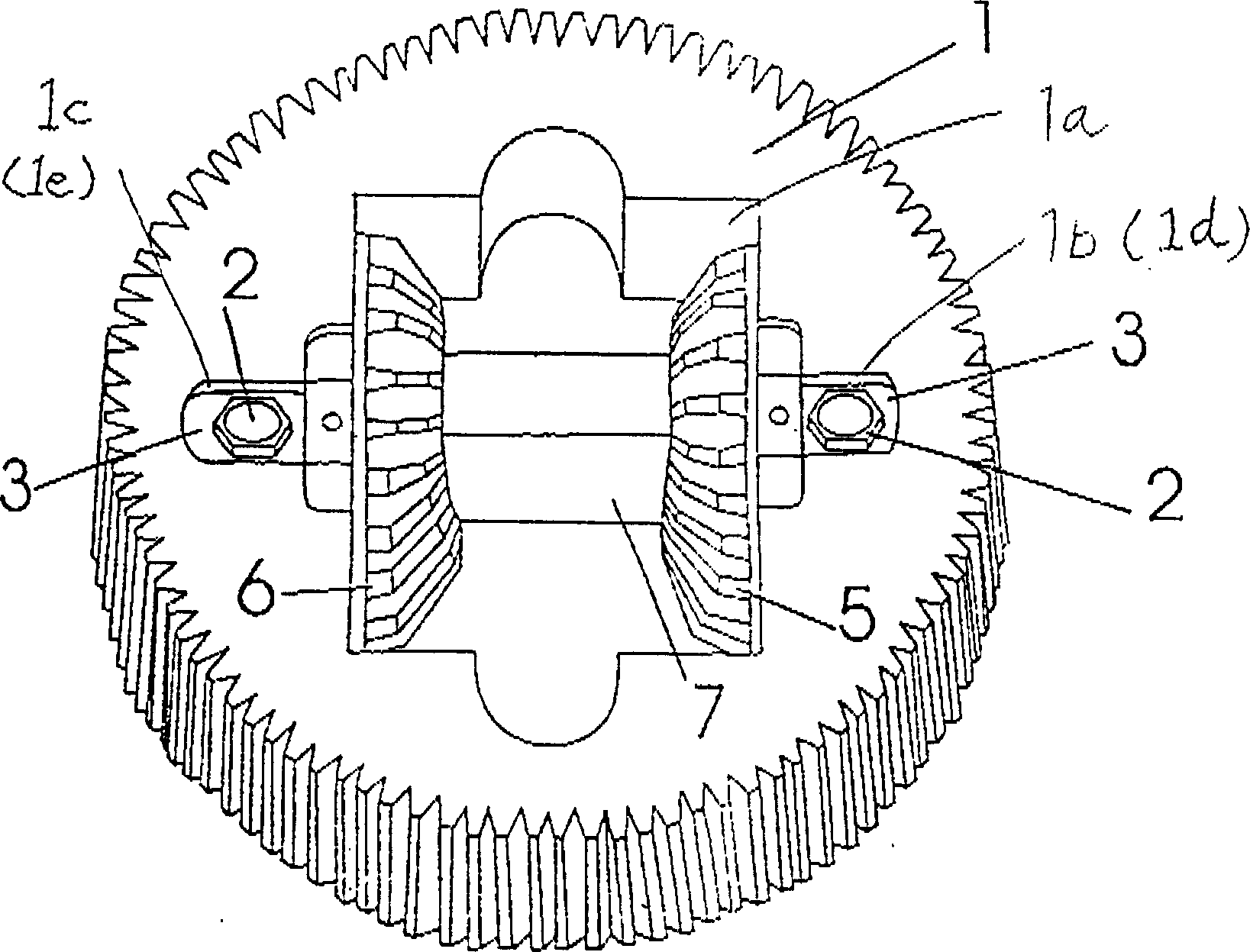
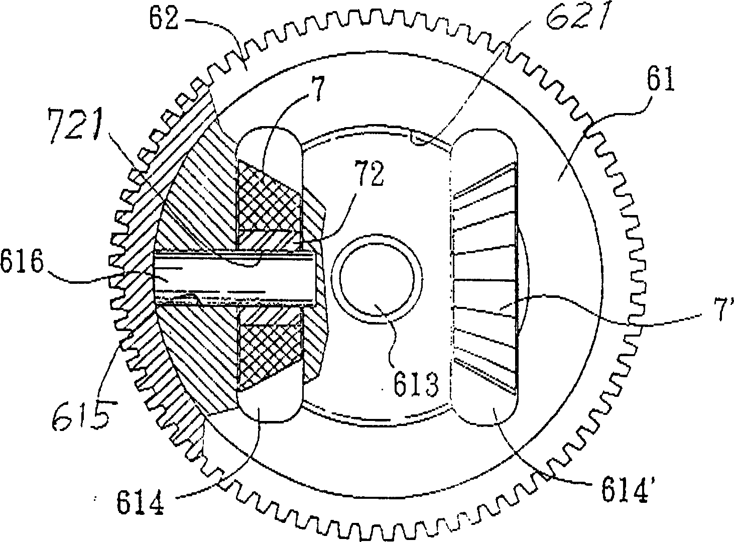
[0029] The manufacture method of differential gear of the present invention, as Figure 3 to Figure 9 , the manufacturing process of the drive bull gear 1 of the differential is described as follows:

[0030] The process includes:

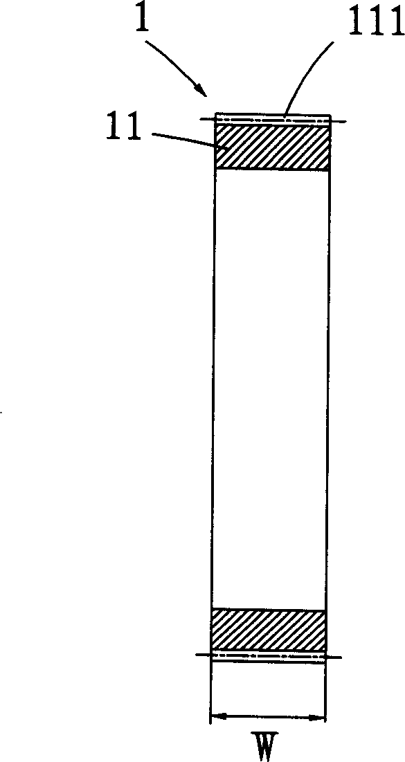
[0031] (A) Get an appropriate width dimension W and a thick steel pipe 11 with a thickness T of 12-15mm, and mill an external tooth 111 at its outer circumference to form a blank for driving the bull gear 1, such as image 3 shown;

[0032] (B) Turning the first and second circular grooves 112, 112' on both sides of the initial blank of the driving gear 1, such as Figure 4 As shown, its depth is less than 1 / 2 width W, thus forms an intermediate wall 113 between two circular grooves;

[0033] (C) Drill a plurality of holes 114 at equal intervals on the intermediate wall 113, such as Figure 5 shown;

[0034] (D) Place the differential small helical gear shafts 12, 12 with C-shaped buckle grooves 121, 121 in the inner peripheral space of the in...


PUM


Abstract

A method of manufacturing a differential gear comprises, adapting external toothings with thick steel tubes, casting the thick steel tube, the cast aluminium part, two axles of two differential bevelwheels integrally by the cast aluminum method to drive the germule of a gearwheel, then installing and fixing the first pair of differential bevel wheels into the axis; flanges of covers of the rightand left bevel wheels supporting the second pair of differential bevel wheels, are engaged with concaves on two sides of the gearwheels, to drive the gearwheels, two pairs of differential bevel wheels, covers of the right and left bevel wheels, the right and left axles. By the invention, a differential gear could be accurately fixed in the center line, and two axles after assembling wouldn't produce noise and swing, which improves great the quality of the differential gear.

Description

technical field [0001] The invention relates to a manufacturing method of a differential gear. Background technique [0002] Existing differential has the No. 89203027 of new patent application, the structural improvement of the electric scooter differential of No. 429901 of patent announcement number (as figure 1 Shown, that is, the accompanying drawings of the invention figure 1 ); and No. 89203736, the improved structure of the differential gear of Patent Publication No. 433193 (such as figure 2 Shown, promptly this pattern pattern No. 5 figure). [0003] As far as the driving wheel 1 of the above-mentioned previous case is concerned, the driving wheel is disclosed to be made of a hollow square groove 1a by powder forming stamping, and a groove 1b, 1c, 1d with locking holes 1f, 1g is provided on the left and right sides respectively. , 1e, and then put the two umbrella-shaped differential wheels 5, 6 into the left and right sides of the positioning shaft 7 respectivel...

Claims


Application Information

Patent Timeline
Patent Type & Authority Applications(China)
IPC IPC(8): B23P15/14
Inventor 陈李烨
Owner 陈李烨
Why Eureka
Try Eureka