
Running fix test mechanism

A testing mechanism and mobile positioning technology, applied in the direction of measuring devices, mechanical devices, mechanical measuring devices, etc., can solve the problems of large gantry span, limited equipment positioning, and difficult motor drive, etc., to achieve reduced structural strength requirements and stable operation , cost reduction effect

Inactive Publication Date: 2009-06-17
东莞晨真光伏有限公司
View PDF1 Cites 9 Cited by
  • Summary
  • Abstract
  • Description
  • Claims
  • Application Information

AI Technical Summary

Problems solved by technology

[0004] It can be seen that the gantry structure generally supports the beam on both sides through the support column. From the perspective of force, the equipment is installed in the middle of the beam, and the load on the beam is relatively large, but there is only support on both sides. Therefore, the gantry of the beam The span is very large, and the design and manufacture of the mechanical structure are high, while reducing the span of the gantry limits the positioning of the equipment in the lateral direction
In addition, when the longitudinal coordinates of the gantry are positioned along the longitudinal direction, the supporting columns on both sides need to be fed synchronously to achieve accurate positioning, that is, both sides of the supporting columns need to be driven at the same time, which makes the motor drive difficult and the cost of the driving system is high.

Method used


Image

  • Running fix test mechanism
  • Running fix test mechanism
  • Running fix test mechanism

Examples


Embodiment Construction

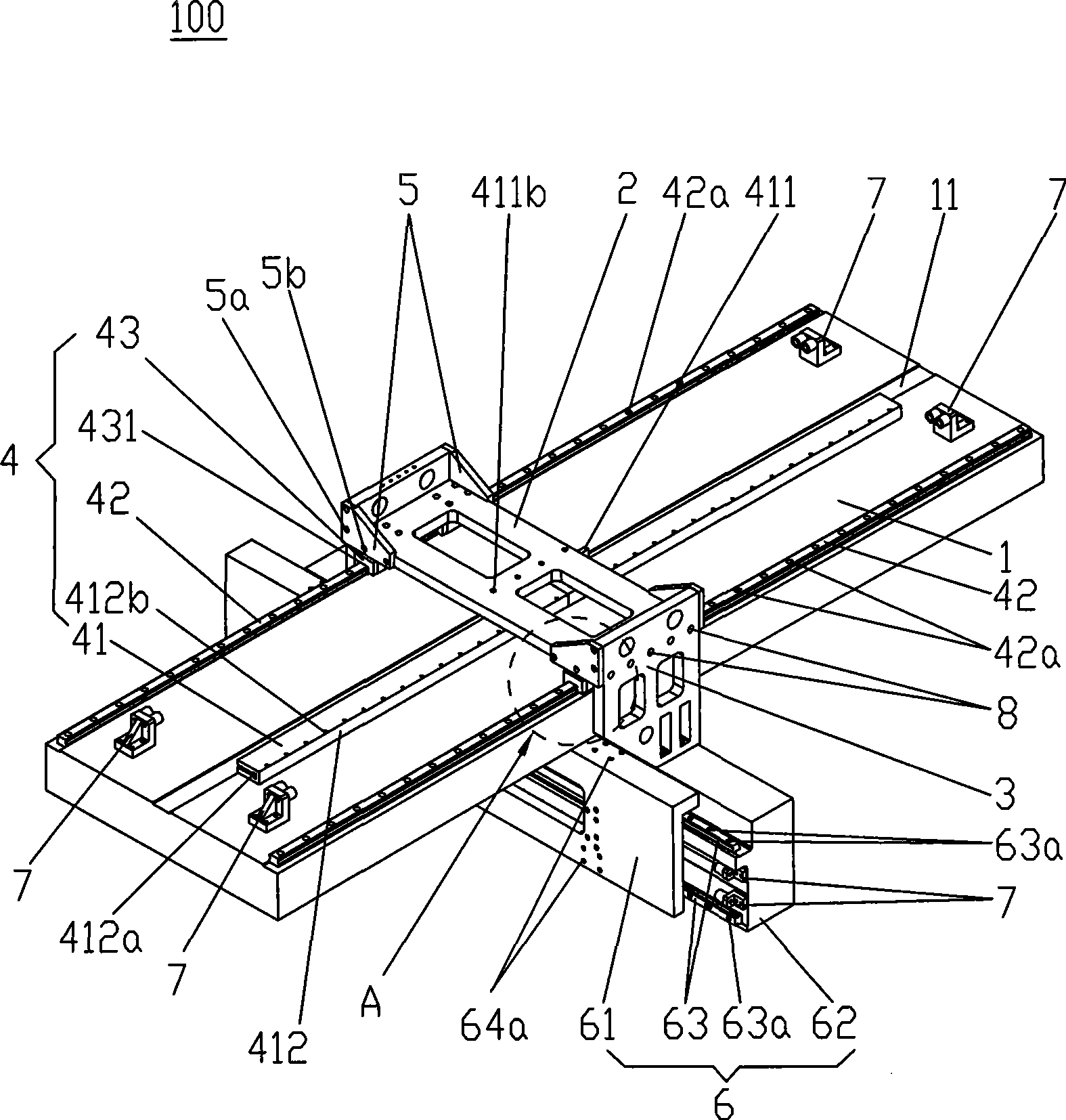
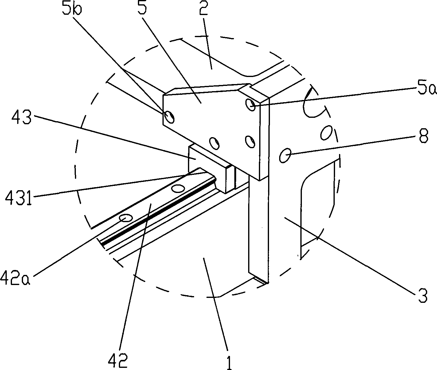
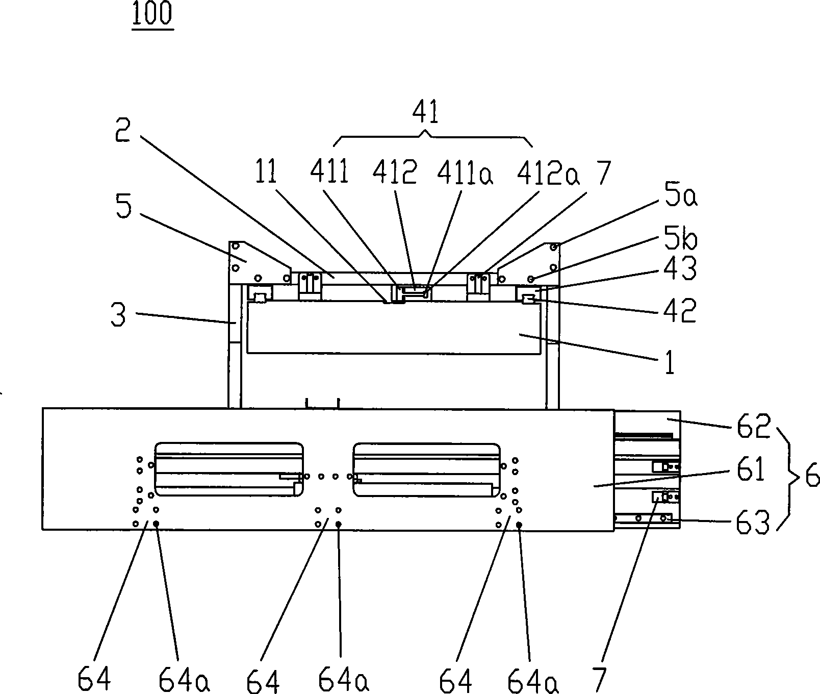
[0021] Such as figure 1 , figure 2 As shown, the mobile positioning testing mechanism 100 of the present invention includes a base plate 1, a crossbeam 2, and a boom frame 3. The base plate 1 is fixed on the workbench, the crossbeam 2 spans the base plate 1, and the boom The frame 3 is connected to both ends of the crossbeam 2 across the base plate 1 through screws 8. The mobile positioning test mechanism 100 of the present invention also includes a driving device 4, and the driving device 4 includes a linear motor 41, a first slide rail 42, And the first chute block 43 that has chute 431, described first slide rail 42 is installed on the longitudinal (long side direction of substrate) both sides of described substrate 1 by screw 42a, described first chute block 43 Fixedly installed on the beam 2 and the chute 431 is stuck on the first slide rail 42, one end of the linear motor 41 is fixed on the substrate 1 by a screw 42a along the longitudinal direction of the substrate 1,...


PUM


Abstract

The invention discloses a movable positioning testing mechanism, comprising a baseplate, a beam, a suspension arm support; wherein, the baseplate is fixed on a workbench, the beam spans over the baseplate, the suspension arm support is connected with the two ends of the beam; the mechanism also comprises a drive device which comprises a linear motion actuator, a first dump rail and a first chute block provided with a chute; wherein, the first dump rail is arranged on the two longitudinal sides of the baseplate, the first chute block is arranged on the beam and the chute is blocked on the first dump rail, one end of the linear motion actuator is fixed on the baseplate along the longitudinal direction of the baseplate and the other end thereof is fixed on the beam. As the two ends of the beam of the invention are connected with the suspension arm support for suspending objects to be tested, when the objects to be tested is under the baseplate during operation, the pressure on the beam is greatly reduced; in addition, the dump rails are arranged on the two sides of the baseplate and the linear motion actuator is used to drive the beam, so that only one linear motion actuator is needed to ensure stable operation of the beam. The invention has simple and reasonable design and effectively reduces the cost.

Description

technical field [0001] The invention relates to a two-axis testing mechanism, in particular to a mobile positioning testing mechanism used for the development of a two-axis testing platform. Background technique [0002] At present, the two-axis test platform mainly adopts the gantry structure. The gantry structure is composed of the gantry loaded with the short axis (transverse axis) and the longitudinal axis of the gantry. The detection equipment is installed on the slider of the longitudinal axis for longitudinal coordinate positioning. It also bears the longitudinal axis and carries out horizontal coordinate positioning along the horizontal axis direction, thereby realizing the precise positioning of the testing equipment in the entire testing plane. [0003] Chinese Patent No. 200720148242.0 discloses a gantry structure, which includes a base, and support columns of equal height are respectively arranged on the left and right sides of the base, and the left and right si...

Claims


Application Information

Patent Timeline
Patent Type & Authority Applications(China)
IPC IPC(8): G01D11/00G01D11/16
CPCG01B5/00
Inventor 杨明生覃海蓝劾王勇
Owner 东莞晨真光伏有限公司
Learn More