Common mode noise and differential mode noise separator for conductive electromagnetic interference noise
A technology of electromagnetic interference and common mode noise, applied in the direction of noise figure or signal-to-noise ratio measurement, circuits, transformers, etc.
- Summary
- Abstract
- Description
- Claims
- Application Information
AI Technical Summary
Problems solved by technology
Method used
Image
Examples
Embodiment
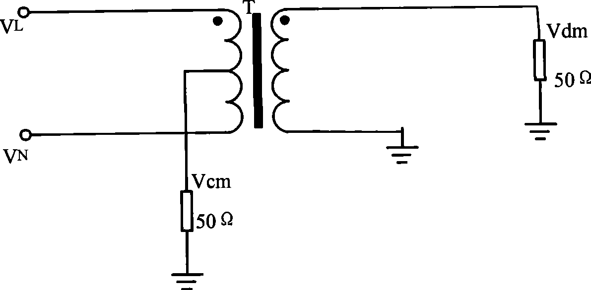
[0050] 4 is the circuit schematic diagram of the common mode noise and differential mode noise separator (CM / DM separator for short) of conductive electromagnetic interference noise of the present invention. Flow ring L, differential mode filter capacitor C and double-pole double-throw switch. The differential mode filter capacitor C is connected in parallel to the primary side of the RF transformer T, and the common mode output is connected to the midpoint tap of the primary side of the RF transformer T; the secondary side of the RF transformer T is respectively connected to the two input terminals of the common mode choke coil L, and the differential mode The signal is output through the output end of the common mode choke coil L, while the other output end of the common mode choke coil L is grounded to form a loop. Select the transformer model Mini-Circuis: T2-1T-X65, select 10μF for filter capacitor C, and double-pole double-throw switch to control the work of the common-m...
PUM
 Abstract
Description
Claims
Application Information
 - R&D
- Intellectual Property
- Life Sciences
- Materials
- Tech Scout
- Unparalleled Data Quality
- Higher Quality Content
- 60% Fewer Hallucinations
Browse by: Latest US Patents, China's latest patents, Technical Efficacy Thesaurus, Application Domain, Technology Topic, Popular Technical Reports.
© 2025 PatSnap. All rights reserved.Legal|Privacy policy|Modern Slavery Act Transparency Statement|Sitemap|About US| Contact US: help@patsnap.com


