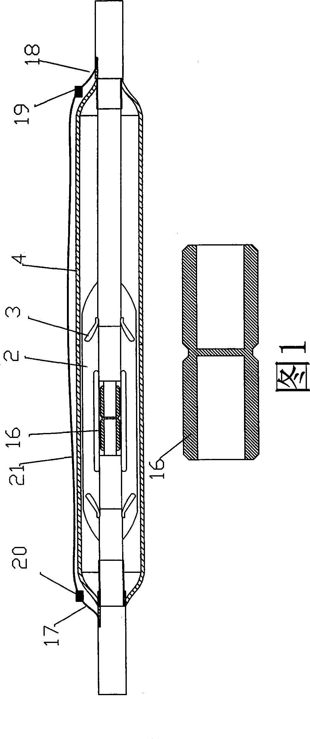
Middle joint of high voltage electric cable for connecting composite optical fiber and connecting method

A high-voltage cable and composite optical fiber technology, which is applied in the direction of cable joints, optical waveguide coupling, etc., can solve problems such as tension, low mechanical strength of optical fibers, and influence

Active Publication Date: 2009-06-17
BANDWEAVER TECH CO LTD
View PDF3 Cites 23 Cited by
  • Summary
  • Abstract
  • Description
  • Claims
  • Application Information

AI Technical Summary

Problems solved by technology

There is a certain loss and unreliability at the fiber splicing point, which has a negative impact on DTS temperature measurement
Another significant disadvantage of the built-in type is that due to the location of the optical fiber, the cable may be under tension during the manufacturing, coiling, transportation, installation and operation stages.
The mechanical strength of optical fiber is very low, once damaged, it cannot be repaired

Method used


Image

  • Middle joint of high voltage electric cable for connecting composite optical fiber and connecting method
  • Middle joint of high voltage electric cable for connecting composite optical fiber and connecting method
  • Middle joint of high voltage electric cable for connecting composite optical fiber and connecting method

Examples


Embodiment 1

[0053] Figure 5 It is a schematic diagram of Embodiment 1 of the method for connecting a high-voltage cable of a composite optical fiber with an intermediate joint of the present invention. This figure has described a kind of installation method utilizing the middle joint of the high-voltage cable that connects composite optical fiber, and this method comprises the following steps:

[0054] The first step is to make cable ends for the first cable and the second cable to be connected, and strip off the first center conductor 6 and the second center conductor 7 therein;

[0055] The second step is to pull out the first optical cable 11 from the first center conductor 6 of the first cable, pass the first optical cable 11 through the first chamber 8, the channel 5 and the second chamber 9 in turn, and from the second chamber 9 to wear a certain length;

[0056] Step 3 Insert the first center conductor 6 into the first cavity 8 and abut against the partition 10 . Pull out the s...

Embodiment 2

[0060] Image 6 It is a schematic diagram of Embodiment 2 of the method for connecting the high-voltage cable of the composite optical fiber with the intermediate joint of the present invention. This figure has described a kind of installation method utilizing the middle joint of the high-voltage cable that connects composite optical fiber, and this method comprises the following steps:

[0061] The first step is to make cable ends respectively for the first cable and the second cable to be connected, and strip off the first center conductor 6 and the second center conductor 7 respectively;

[0062] The second step pulls out the first optical cable 11 from the first central conductor 6 of the first cable, passes the first optical cable 11 through the guide tube 14 and exposes an appropriate length, the guide tube 14 is made of copper material, and There is a disc-shaped protrusion 15 at the middle part. The outer diameter of the guide tube 14 is loosely fitted with the inner ...


PUM


Abstract

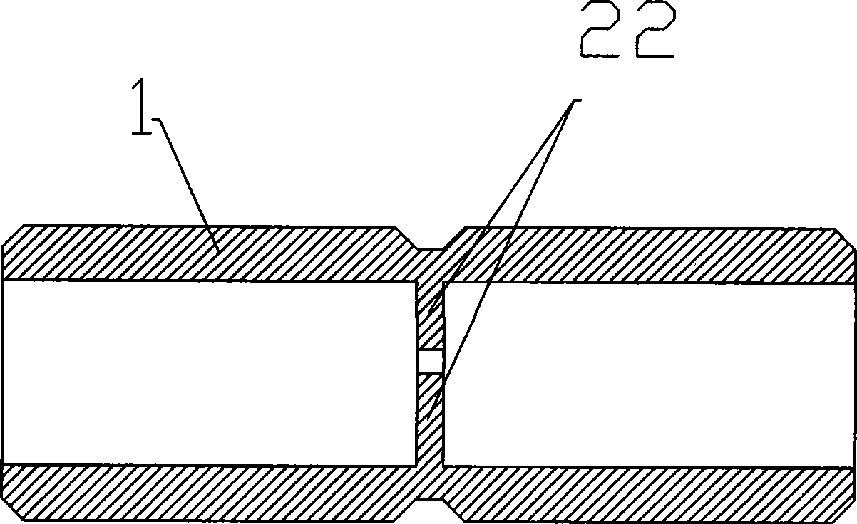
The invention relates to an intermediate connector of an optical fiber composite high-voltage cable, which comprises a conductor connecting member, an insulating and stress balancing unit and a metal outer case, wherein the conductor connecting member is a pipe with one longitudinal H-shaped section, the middle part of the pipe is equipped with a partition board, two sides of the partition board are cavities communicated with the outside, two conductor ends of the high-voltage cable can be respectively disposed in the cavities on the two sides of the partition board inside the conductor connecting member, the outside of the conductor connecting member is sequentially connected with the insulating and stress balancing unit and the metal outer case, and the partition board is equipped with at least one passage contained in the high-voltage cable conductor for penetrating with an optical cable. The intermediate connector realizes electrical and optical connection of the optical fiber composite high-voltage electric cable.

Description

technical field [0001] The invention relates to cable connection, in particular to an intermediate joint of a high-voltage cable compounded with optical fibers and a method for using it to connect two high-voltage cables containing optical cables. Background technique [0002] In order to ensure the safe operation of the high-voltage underground cable system, the power sector needs to monitor it online. The main contents of online monitoring include load monitoring and fault monitoring. [0003] The constraints of the cable load capacity mainly come from the allowable operating temperature limit of the cable and cable accessories manufacturing materials. For example, for XLPE cables, the temperature of the cable conductor, that is, the temperature of the XLPE adjacent to the conductor, is usually specified not to exceed 85°C or 90°C. In the design of cables and cable systems, the load capacity design is mainly completed according to the temperature limit of the conductor. ...

Claims


Application Information

Patent Timeline
Patent Type & Authority Applications(China)
IPC IPC(8): H02G15/08G02B6/36
Inventor 杨峰张成先张东明赵浩曹进林宗强
Owner BANDWEAVER TECH CO LTD
Why Eureka
Try Eureka