Network deployment method, network system and IP node

A network deployment and network system technology, applied in the field of network deployment methods, network systems and IP nodes, can solve problems such as IP layer oscillation, and achieve the effect of solving the oscillation problem

Active Publication Date: 2009-06-17
HUAWEI TECH CO LTD
View PDF2 Cites 14 Cited by
  • Summary
  • Abstract
  • Description
  • Claims
  • Application Information

AI Technical Summary

Problems solved by technology

[0007] In order to solve the problem that the existing multi-layer network composed of IP and optical transport layer will cause the oscillation of the IP l

Method used


Image

  • Network deployment method, network system and IP node
  • Network deployment method, network system and IP node
  • Network deployment method, network system and IP node

Examples


Embodiment 1

[0029] see Figure 4 , the embodiment of the present invention provides a network deployment method, specifically including:

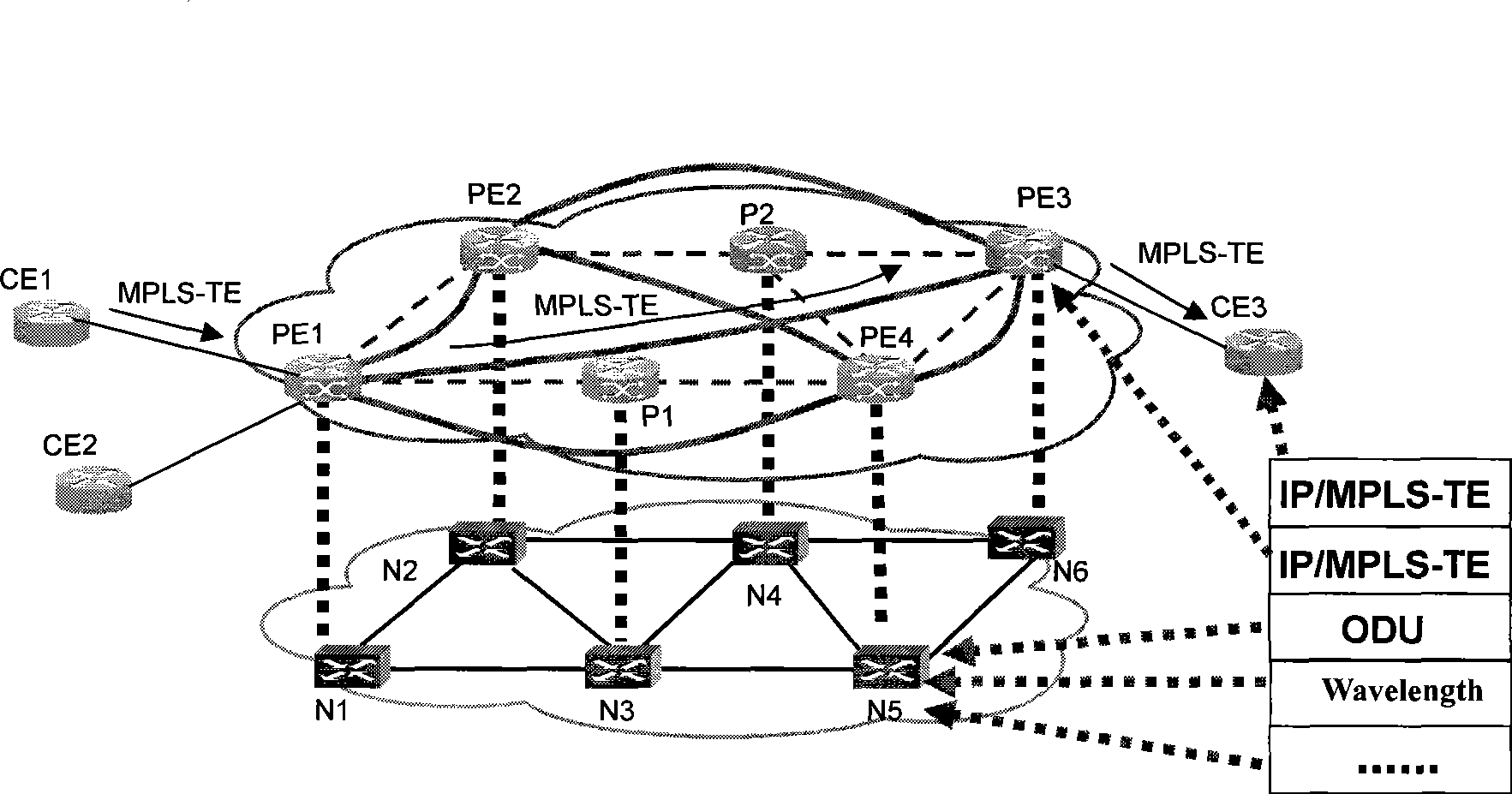
[0030] Step 101: Establish a connection-oriented packet transport layer between the IP layer and the optical transport layer, such as the MPLS-TE layer.

[0031] The MPLS-TE layer is used to carry the IP layer, and the optical transport layer is used to carry the MPLS-TE layer.

[0032] In specific applications, MPLS-TE can also be replaced by other connection-oriented packet transport layers, such as PBT (Provider Backbone Transport, carrier backbone network transport), T-MPLS (Transport Multi-protocol Label Switching, transport multi-protocol label switching), etc.

[0033] When MPLS-TE is used, it is implemented through routers. In order to implement IP and MPLS-TE exchange at the same time on the IP node, you can use a router that supports both IP and MPLS-TE.

[0034] When PBT or T-MPLS is adopted, it is realized through special equipment suppo...

Embodiment 2

[0054] see Figure 7 , the embodiment of the present invention provides a network deployment method, specifically including:

[0055] Step 201: Establish a connection-oriented packet transport layer between the IP layer and the optical transport layer, such as the MPLS-TE layer.

[0056] The MPLS-TE layer is used to bear the IP layer, and the MPLS-TE is set so that when the MPLS-TE layer changes, the IP layer does not change with the MPLS-TE layer. The optical transport layer is used to carry the MPLS-TE layer. When the optical transport layer changes, the MPLS-TE layer will change accordingly.

[0057] In specific applications, MPLS-TE can also be replaced by other connection-oriented packet transport layers, such as PBT and T-MPLS.

[0058] In order to implement IP and MPLS switching at the same time on IP nodes, routers that support both IP and MPLS-TE can be used.

[0059] Establish a channel with a connection-oriented packet transport layer between any two IP nodes as ...

Embodiment 3

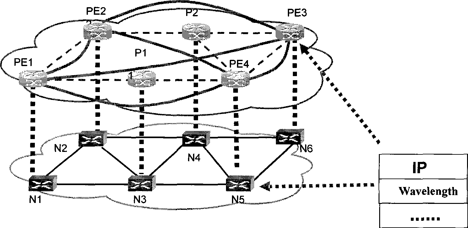
[0081] see figure 2, the embodiment of the present invention provides a network system, including an IP layer composed of routers and an optical transport layer composed of WDM equipment located below it, an MPLS-TE layer is also included between the IP layer and the optical transport layer, and the IP layer includes The IP node, the IP node includes a connection establishment module, which is used to set up a channel with a connection-oriented packet transport layer between any two IP nodes as a link between the two IP nodes, specifically:

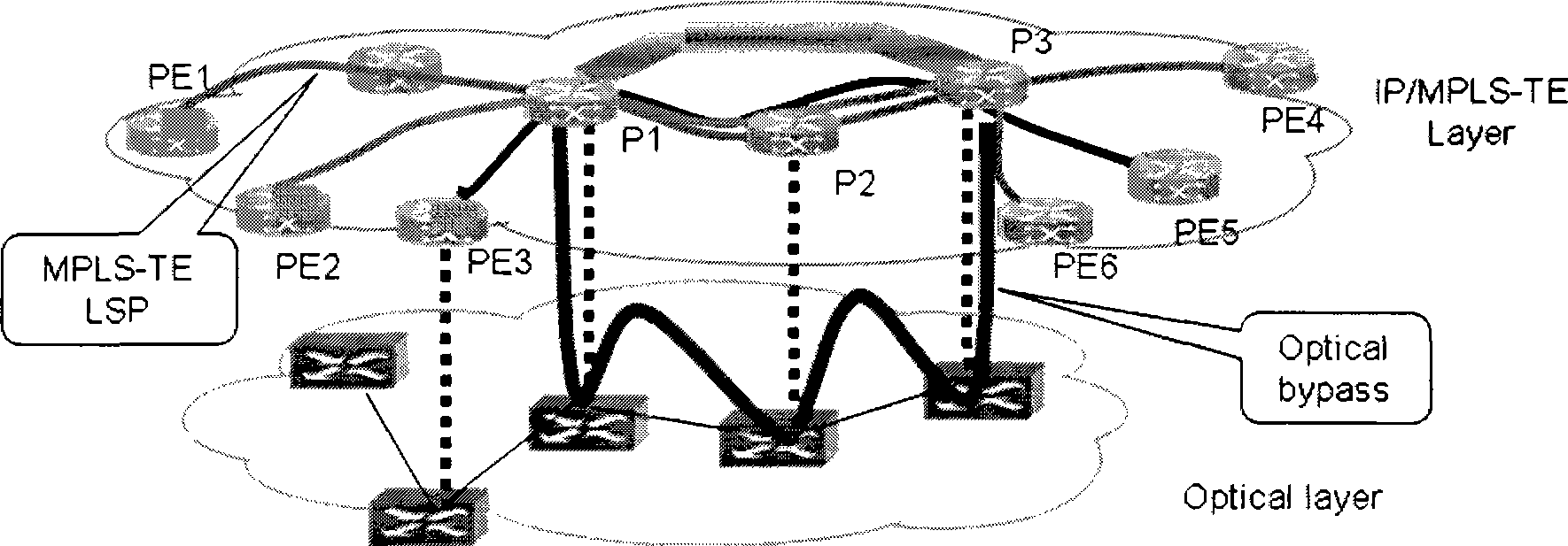
[0082] Establish an MPLS-TE LSP between any two IP nodes as an IP layer link. The WDM equipment is specifically a DWDM equipment or a DWDM equipment with an OTN capability.

[0083] The connection establishment module specifically includes:

[0084] The MPLS-TE connection establishment unit is used to establish an MPLS-TE LSP as an IP layer link between any two IP nodes;

[0085] The flow monitoring unit is used to monitor the flow ch...


PUM


Abstract

The invention discloses a network deploying method, a network system and an IP node, which belong to the technical field of broadband internet, wherein the method comprises establishing a packet transmission layer with connection-oriented between an IP layer and an optical transport layer, and establishing a channel of the packet transmission layer with connection-oriented between any two IP nodes as a link between two IP nodes. The system comprises an IP layer and an optical transmission layer arranged on the lower layer of the IP layer, wherein a packet transmission layer with connection-oriented is further arranged between the IP layer and the optical transmission layer, and the IP layer comprises an IP node. The IP node comprises a connection establishing module. The network deployingmethod separates the IP layer from the optical transmission layer through establishing an MPLS-TE layer between the IP layer and the optical transmission layer and establishing LSP of the MPLS-TE between any two IP nodes as a link, and solves the oscillation of the IP layer.

Description

technical field [0001] The invention relates to the technical field of broadband Internet, in particular to a network deployment method, a network system and an IP node. Background technique [0002] With the rapid development of broadband Internet and the popularization of various applications, network traffic is increasing rapidly every year, requiring a large-capacity core bearer network for transmission. The current multi-layer network composed of IP and optical transport layer requires the network to be able to adapt to dynamic bandwidth requirements due to frequent changes in network traffic. A current network construction idea is that the IP layer adopts router networking, and the routers are connected through static point-to-point WDM (Wavelength Devision Multiplexing, wavelength division multiplexing) devices to provide links. Since the forwarding mode adopted by the router is packet-by-packet forwarding, it is not suitable for transmission that requires cascade tr...

Claims


Application Information

Patent Timeline
IPC IPC(8): H04L12/56H04L29/06H04L45/50
CPCH04L45/50H04L45/62H04L45/00
Inventor 何健飞徐慧颖杨志军
Owner HUAWEI TECH CO LTD
Why Eureka
Try Eureka