Cutting tool and cutting insert

A technology of cutting inserts and cutting tools, applied in the direction of milling cutting inserts, manufacturing tools, milling cutters, etc., can solve the problems of surface finishing of cutting materials W, large connection angle, and increased cutting resistance.

Active Publication Date: 2009-06-17
MITSUBISHI MATERIALS CORP
View PDF2 Cites 20 Cited by
  • Summary
  • Abstract
  • Description
  • Claims
  • Application Information

AI Technical Summary

Problems solved by technology

[0015] However, when such a cutting insert 1 is configured such that a minor cutting edge 3A formed on a corner portion 4A of a heptagonal surface protruding radially outward and forward in the cutting depth direction of the tool body is substantially perpendicular to the above-mentioned axis ,like Figure 9 As shown, in the case where the surface of the workpiece W forms a vertical wall perpendicular to the feeding direction of the tool body, a pair of flat portions formed on the corner portion 4B adjacent to the tool body rear end side of the corner portion 4A One of them interferes with the vertical wall, and the minor cutting edge 3B formed on the flat portion cuts, which may lead to an increase in cutting resistance
That is, although it is intentionally formed into a heptagonal plate shape and the angle formed by the adjacent cutting edges 2 is reduced, the connection angle between the pair of flat parts provided to form the minor cutting edge 3 is too large, so it is different from the The octagonal flat cutting insert also interferes with the workpiece W
[0016] Therefore, in such a case, since abnormal vibration (high-frequency vibration) occurs due to an increase in cutting resistance, there is a problem that it is difficult to finish the surface of the material W to be cut into state of contentment

Method used


Image

  • Cutting tool and cutting insert
  • Cutting tool and cutting insert
  • Cutting tool and cutting insert

Examples


Embodiment Construction

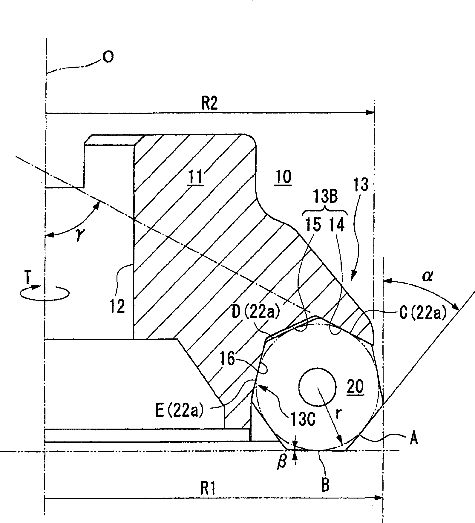
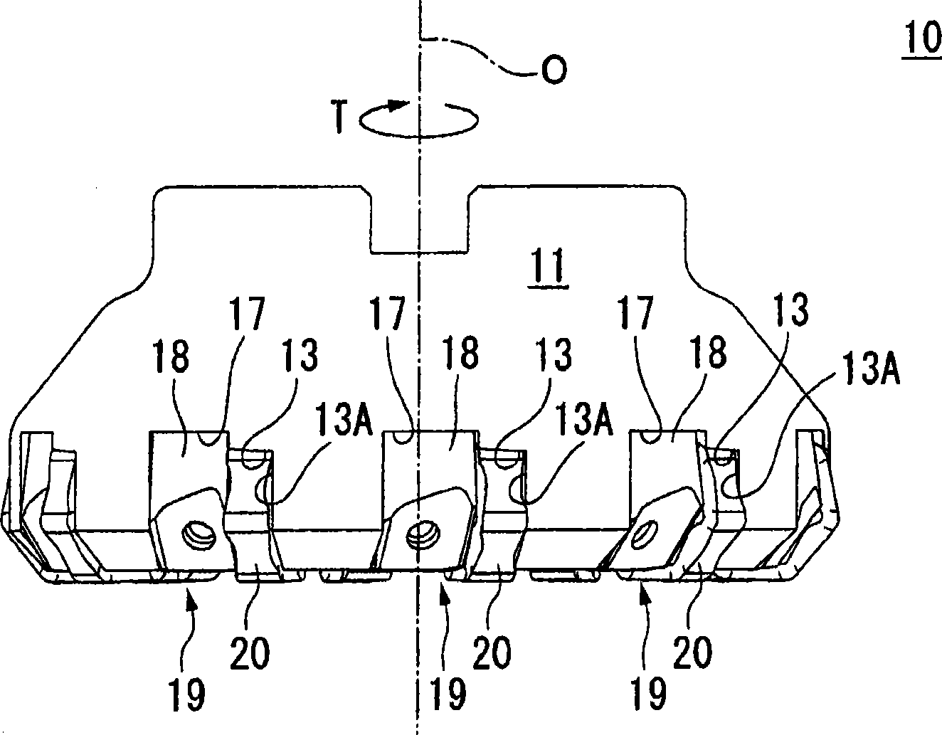
[0057] Embodiments of the present invention will be described with reference to the drawings. Figure 1 to Figure 3 A milling cutter as a cutting tool according to the present embodiment is shown. In addition, Figure 4 to Figure 7 Indicates the cutting insert mounted on this milling cutter. In addition, the milling cutter of this embodiment looks rightward toward the surface to be processed ( figure 1 The so-called right-hand knife that rotates in the T direction) and is equipped with the cutting blade of the right-hand knife.

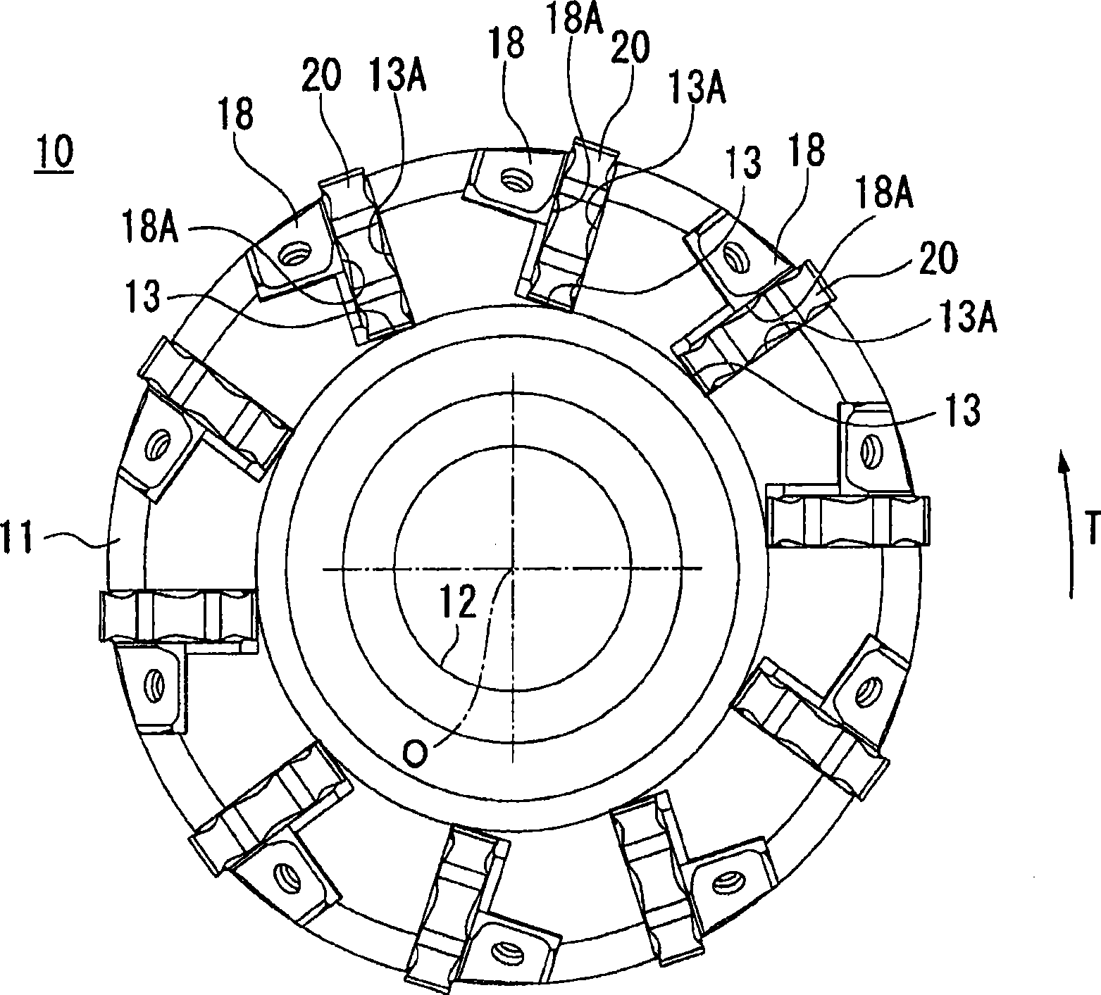
[0058] The milling cutter 10 is used when performing plane machining on cast iron or steel and other cut materials, such as figure 2 and image 3 As shown, the milling cutter 10 has a substantially disc-shaped tool body 11 centered on the axis 0 . A mounting hole 12 extending along the axis 0 is bored in the tool body 11 .

[0059] On the outer periphery of the front end of the tool main body 11, a mounting seat 13 for mounting a cutting inser...


PUM


Abstract

A cutting tool comprising a tool body being turned about the axis, and a cutting insert fixed removably to the outer circumference at the tip of the tool body. The cutting insert has a front / back-reversal symmetric substantially regular heptagonal plane shape having two heptagonal faces parallel with each other, a side face continuous to each heptagonal face at right angle, and a cutting edge provided at each ridge line between the heptagonal face and the side face. The cutting edge includes a main cutting edge projected onto the side of the regular heptagon, and sub-cutting edges extending from the opposite ends of each main cutting edge to incline toward the center of the heptagonal face and connecting the adjoining main cutting edges. The tool body is equipped with a fixing seat for holding the cutting insert such that one main cutting edge is directed toward the tip side of the tool body and in the radial-outer direction in order to allow it to participate in the cutting, and the corner angle a between the main cutting edge and the axis satisfy a relation 40 DEG<=alpha<=44 DEG .

Description

technical field [0001] The present invention relates to a cutting tool used for surface machining of a material to be cut, and a cutting insert detachably attached to the cutting tool. [0002] this application claims priority based on Japanese Patent Application No. 2006-157050 for which it applied on June 6, 2006, and uses the content here. Background technique [0003] Conventionally, as a cutting tool used when cutting a workpiece, for example, a cutting tool in which an insert having a cutting edge is detachably mounted on the outer periphery of the front end portion of the tool body as shown in Patent Document 1 is known. tool. [0004] The cutting tool disclosed in Patent Document 1 rotates at a high speed around the axis of the tool body, and feed is applied in a direction perpendicular to the axis direction of the tool body. The main cutting edge in the direction of depth of cut) and the radially outer side cut the surface of the material to be cut. [0005] Amon...

Claims


Application Information

Patent Timeline
Patent Type & Authority Applications(China)
IPC IPC(8): B23C5/06B23C5/20
CPCB23C2200/125B23C2200/201B23C2200/206B23C5/06B23C2210/206B23C2210/0407B23C2200/366B23C5/207B23C2200/0488B23C2200/208B23C2200/205Y10T407/23Y10T407/1924Y10T407/235B23C5/202B23C5/20B23B27/16B23B27/14
Inventor 高桥秀史成田彻
Owner MITSUBISHI MATERIALS CORP
Why Eureka
Try Eureka