Onboard electronic device and vehicle mounting the same

A technology for electronic devices and vehicles, applied in vehicle components, support structure installation, protection against damage caused by electrostatic discharge, etc., can solve the problem of wasting time and energy, and achieve the effect of improving anti-static ability

Inactive Publication Date: 2009-06-17
TOYOTA JIDOSHA KK
View PDF1 Cites 16 Cited by
  • Summary
  • Abstract
  • Description
  • Claims
  • Application Information

AI Technical Summary

Problems solved by technology

[0019] Therefore, workers who perform assembly work need to take adequate measures against static electricity, which wastes time and effort

Method used


Image

  • Onboard electronic device and vehicle mounting the same
  • Onboard electronic device and vehicle mounting the same
  • Onboard electronic device and vehicle mounting the same

Examples


no. 1 approach

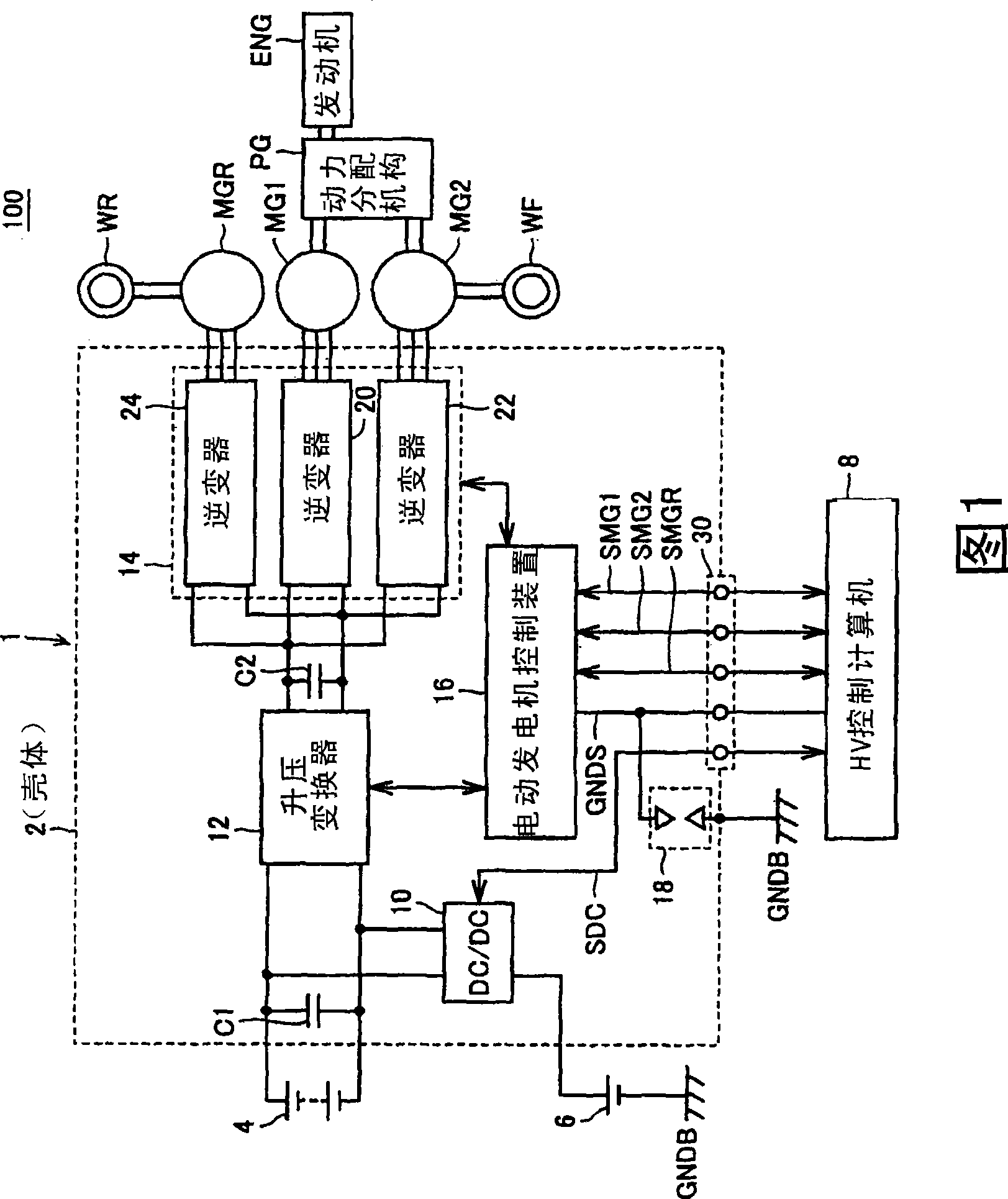
[0057] FIG. 1 is a block diagram showing the configuration of a vehicle 100 according to the embodiment of the present invention.

[0058] Referring to FIG. 1 , a vehicle 100 is a hybrid vehicle including: a high-voltage battery 4, an auxiliary battery 6, an inverter unit 1, an HV (hybrid) control computer 8, motor generators MG1, MG2, and MGR, and a power distribution mechanism PG. , engine ENG, front wheel WF, rear wheel WR.

[0059] Power split mechanism PG is connected to engine ENG and motor generators MG1, MG2 to distribute power between them. For example, the power distribution mechanism may use a planetary gear mechanism having three rotation shafts of a sun gear, a carrier, and a ring gear. These three rotation shafts are connected to the rotation shafts of engine ENG, motor generators MG1, MG2, respectively. A speed reducer related to the rotation shaft of motor generator MG2 may also be mounted inside power split mechanism PG.

[0060] The rotating shaft of motor...

Embodiment approach 2

[0116] In Embodiment 1, the discharge gap was formed between the conductive plate and the case, but the discharge gap may be formed in another part.

[0117] Figure 11 It is a figure for demonstrating the discharge gap of the inverter unit of Embodiment 2.

[0118] Figure 12 is showing Figure 11 The cross-sectional view of the XII-XII section.

[0119] refer to Figure 11 , Figure 12 , the inverter unit 1A also includes: a conductive body ground pattern 194, and an insulating member 155 and a screw 161 as a conductive member that electrically connects the body ground pattern 194 to the housing 102, and the conductive body ground pattern 194 Discharge gap 18A is formed on control substrate 117 between conductive pattern 192 . An external thread is formed at a lower portion of the spacer member 155 , and the external thread portion is screwed into a screw hole formed on the housing 102 . On the upper portion of the spacer member 155, a hole having an internal thread f...


PUM


Abstract

An inverter unit comprises a conductive chassis (2) having ground potential , a control board (17) housed in the chassis (2), and a discharge gap (18), which discharges electricity when a high voltage exceeding a predetermined voltage is applied between a conductive pattern (92) formed on the control board (17) and the chassis (2). Preferably, the inverter unit further comprises a conductive plate (50) that covers the control board (17) and is electrically connected to the conductive pattern (92). The discharge gap (18) is formed between the conductive plate (50) and the chassis (2).

Description

technical field [0001] The present invention relates to a vehicle-mounted electronic device and a vehicle equipped with the same, and particularly relates to a structure for protecting the vehicle-mounted electronic device. Background technique [0002] In order to provide anti-static or anti-overvoltage protection, electronic devices are usually equipped with protection elements for discharging overvoltage. Japanese Patent Application Laid-Open No. 2003-151794 discloses an electronic control device for a motor vehicle equipped with such a protective element. [0003] The electric control device is an electronic control device for a motor vehicle composed of a case ground connected to a casing and an electronic circuit connected to the case ground. Also, the electronic circuit includes: a signal line for transmitting the output signal from the sensor to the integrated circuit, a terminal with the signal line and a connector for control ground, which are arranged between the...

Claims


Application Information

Patent Timeline
Patent Type & Authority Applications(China)
IPC IPC(8): H05F3/04B60R16/06B60R16/02H05K7/14
CPCH05K9/0067
Inventor 广中良臣
Owner TOYOTA JIDOSHA KK
Why Eureka
Try Eureka