Plug structure

A plug and socket body technology, applied in the field of plug structure, can solve problems such as tip discharge, insertion angle deviation, disasters, etc., and achieve the effect of increasing service life

Inactive Publication Date: 2009-06-24
李炎敦
View PDF0 Cites 14 Cited by
  • Summary
  • Abstract
  • Description
  • Claims
  • Application Information

AI Technical Summary

Problems solved by technology

[0004] 1. Generate sharp discharge and high heat, which will cause damage to electrical appliances;
[0005] When the plug structure of the prior art is electrically connected, when the conductive terminal 13 penetrates into the body of the aforementioned power base 20 and gradually approaches the top of the conductive slot 21, the tip of the conductive terminal 13 is often caused by different voltage fluctuations, variable currents, or air. Moisture and other factors lead to instantaneous tip discharge, that is, a powerful arc is generated instantaneously, thereby generating high heat and even locally generating instantaneous high temperature, resulting in melting of the plastic shell of the aforementioned power base 20 body, and causing corrosion of conductive metal The situation will make the surface of the conductive contact rough, increase the resistance, and even damage the structure causing more serious disasters; and the instantaneous current will damage the electronic structure such as the control board of the electrical appliance itself, or cause secondary damage to the charger and other structures. The role of discharge, greatly reducing the life of charging components
[0006] 2. Severe wear, increased resistance and energy consumption;
[0007] see figure 2 As shown in the schematic diagram of the action, when the plug structure of the prior art is electrically connected, it is impossible for the user to always insert the aforementioned power socket 20 at an angle close to the vertical center without bias, and it is possible to complete the power supply at various angles. Insertion action, however, the material of the insertion end of the conductive terminal 13 in the prior art is close to the surface hardness of the aforementioned conductive groove 21, coupled with the deviation of the insertion angle mentioned above for the aforementioned conductive terminal 13, the conductive contact of the inner ring of the conductive groove 21 occurs. The wear of the surface will lead to the accelerated oxidation of the conductive contact surface or the reduction of the conductive contact area and the continuous increase of the resistance due to wear, resulting in an increase in power consumption

Method used


Image

  • Plug structure
  • Plug structure
  • Plug structure

Examples


Embodiment Construction

[0032] The embodiments of the present invention will be described in more detail below in conjunction with the accompanying drawings, so that any worker who is familiar with the technology can implement it after studying the specification.

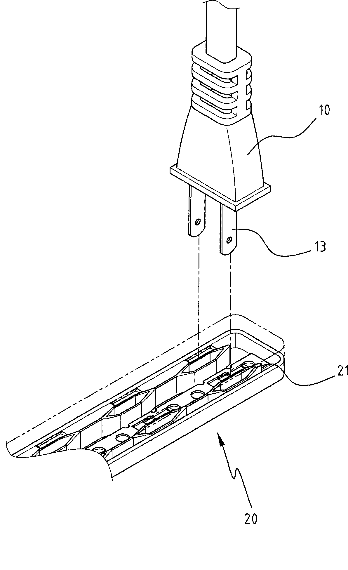
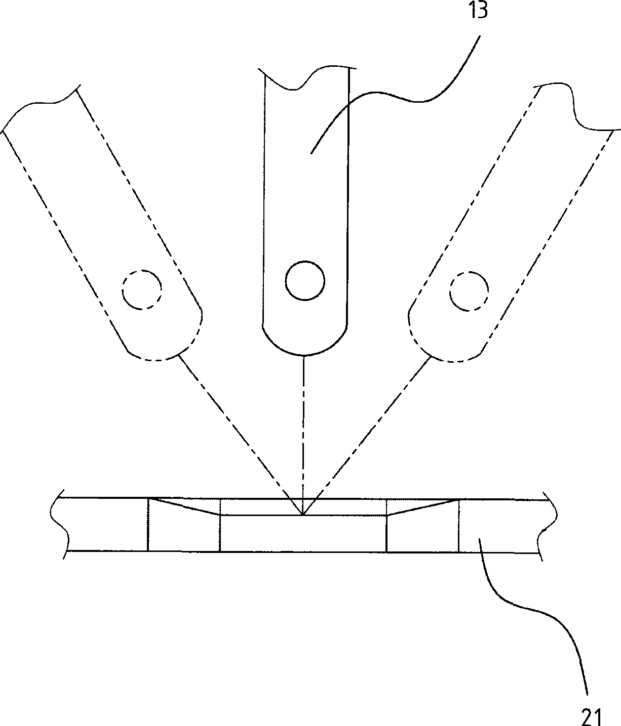
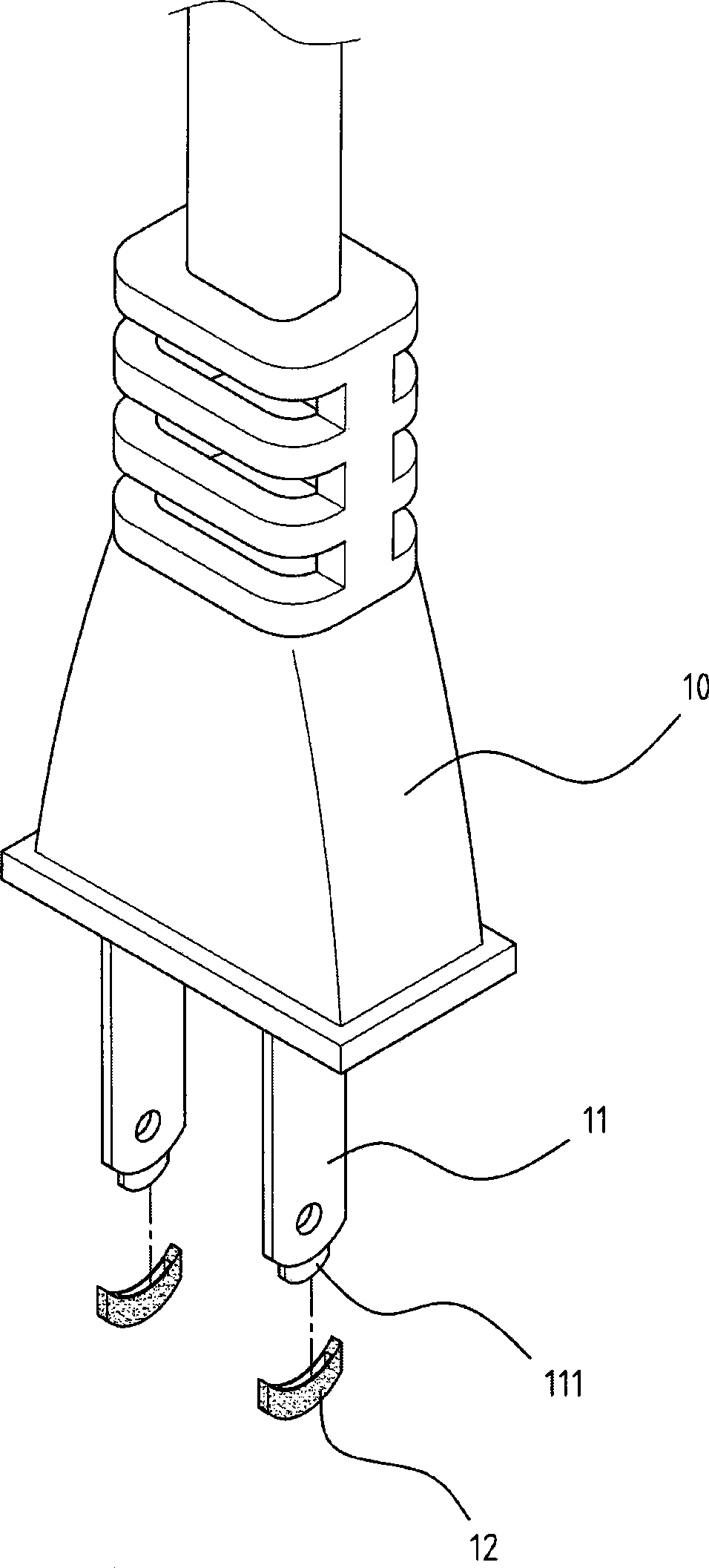
[0033] Please see Figure 3A As shown in the schematic assembly diagram of the structure of the present invention, the plug structure of the present invention has a body size regulated by standard specifications, but according to the plug specifications of various countries, there will be different specifications; Figure 3A It is the standard specification, and the main design feature of the present invention is that the end of the conductive terminal 11 provided on the plug body 10 that is inserted into the power socket 20 is provided with a protruding body whose volume is smaller than the size of the original specification, thereby generating sufficient The space is provided for a certain amount of insulating material to be covered on t...


PUM


Abstract

The invention relates to a lug structure, comprising a plug body which is connected with an electric-conducting terminal and an insulating end; wherein, a sheathing end is arranged at one end that the electric-conducting terminal is connected with an electrical socket outlet; an insulating end is arranged again at the outer edge of the sheathing end; after the insulating end is arranged on the sheathing end, the electric-conducting terminal size with standard specification is formed with the electric-conducting terminal for connecting the power supply; by utilizing the design of the insulating end, the disadvantages that point discharge and high heat are produced when the plug is inserted in the electrical socket outlet are solved, and the efficiency on increasing the service life of the appliance is correspondingly improved; in addition, by utilizing the soft material characteristics of the insulating end, the damage produced by friction with the contact surface of an electric conducting groove in the electrical socket outlet can be greatly reduced when the electric-conducting terminal in inserted in the electrical socket outlet, and the disadvantages that oxidization is caused and resistance is increased are reduced, thus achieving the efficiency on saving electricity and energy.

Description

technical field [0001] The present invention relates to a plug structure. Background technique [0002] see figure 1 The schematic diagram of the plug structure of the prior art shown. In the plug structure of the prior art, the conductive terminal 13 at one end of the power supply connection is usually made of metal with copper material, and its shape is manufactured according to the specifications of the power supply standards of various countries. , when it is connected to the power base 20, it is inserted into the conductive groove 21 provided in the power base to conduct electricity, so as to be used for the electric power of various types of electrical appliances. [0003] However, the aforementioned conductive terminal 13 mainly has several features: 1. the whole is made of the aforementioned conductive metal; However, such features have the following disadvantages when performing the aforementioned electrical connection: [0004] 1. Produce tip discharge and high ...

Claims


Application Information

Patent Timeline
Patent Type & Authority Applications(China)
IPC IPC(8): H01R13/04
Inventor 李炎敦
Owner 李炎敦
Why Eureka
Try Eureka