Digital demodulation method for non-synchronous composite video signal and S video signal

A composite video signal, digital demodulator technology, applied in pulse modulation TV signal transmission, luminance and chrominance signal processing circuits, etc., can solve the problems of high demodulation cost and difficulty in demodulation, and achieve the effect of reducing the area

Active Publication Date: 2009-06-24
HISENSE VISUAL TECH CO LTD
View PDF0 Cites 12 Cited by
  • Summary
  • Abstract
  • Description
  • Claims
  • Application Information

AI Technical Summary

Problems solved by technology

[0006] The purpose of the present invention is to provide a digital demodulation method and demodulator of a non-synchronous composite video signal and S-video sig...

Method used


Image

  • Digital demodulation method for non-synchronous composite video signal and S video signal
  • Digital demodulation method for non-synchronous composite video signal and S video signal
  • Digital demodulation method for non-synchronous composite video signal and S video signal

Examples


Embodiment Construction

[0025] The following is based on Figure 1 to Figure 12 , give a preferred embodiment of the present invention, and give a detailed description, so that the functions and characteristics of the present invention can be better understood.

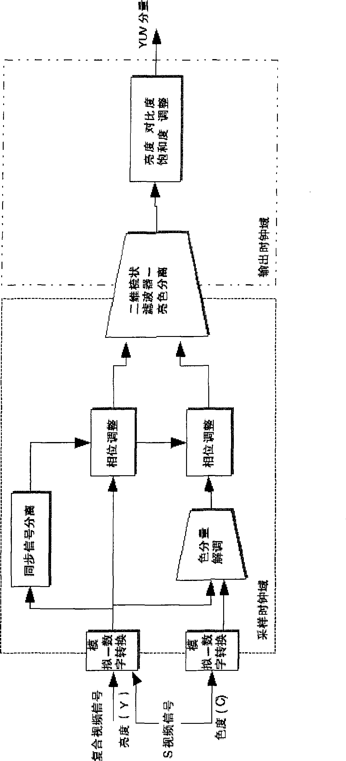
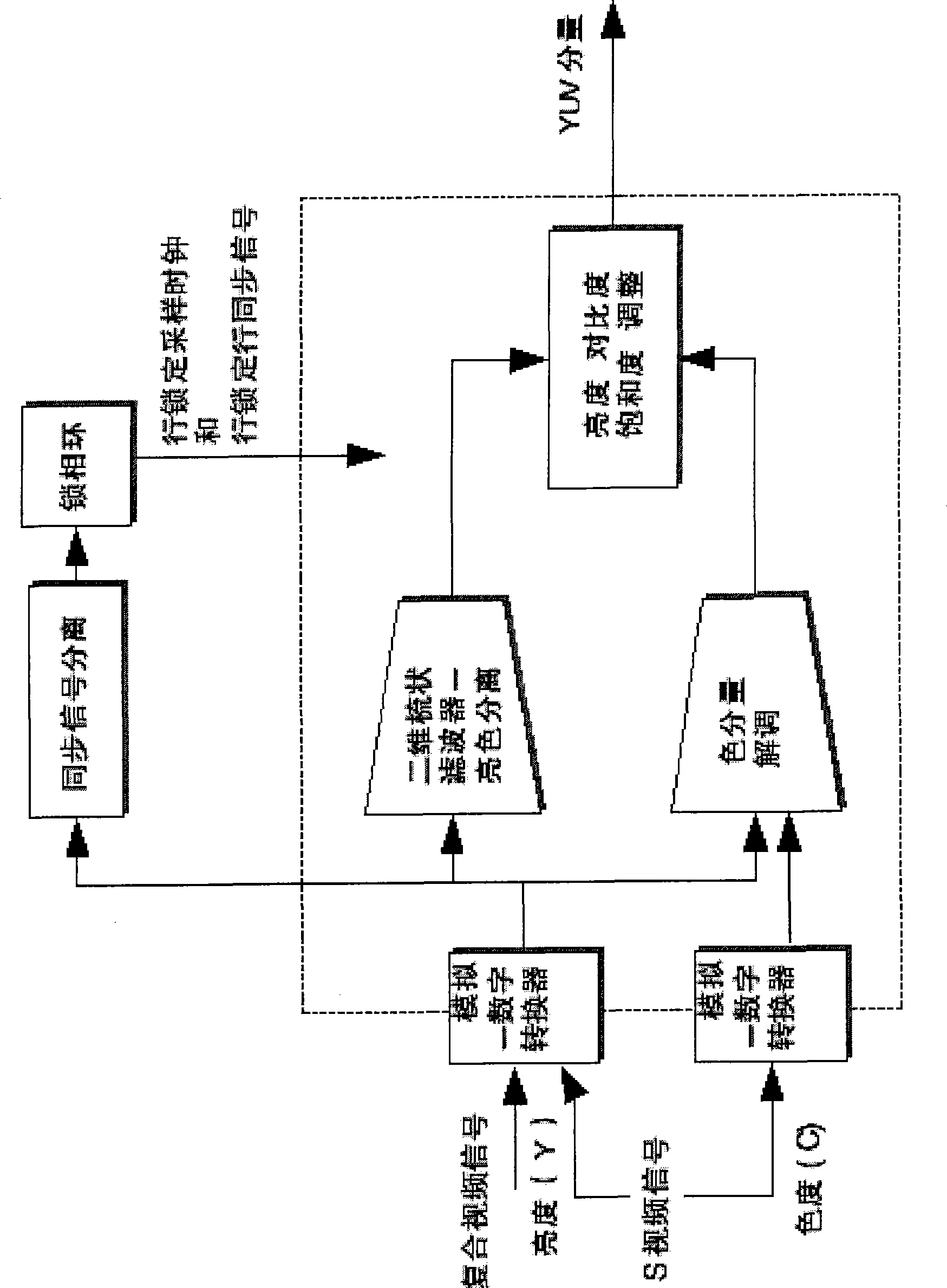
[0026] figure 1 It is a block diagram of a pure digital digital video demodulator, which includes a synchronous signal separation module, a color component demodulation module, a two-dimensional comb filter-bright color separation module and a brightness, contrast, saturation adjustment module. The synchronous signal separation module restores the line synchronous signal and the field synchronous signal from the composite video or S video-luminance signal. The color component demodulation is to judge the system of the current video signal, and use the carrier signal corresponding to the system to perform color demodulation to obtain the color component signal (UV). The two-dimensional comb filter-bright color separation module also uses th...


PUM


Abstract

The invention relates to a digital demodulation method and a demodulator for a non-synchronous composite video signal and an S video signal. The method comprises the following steps: a fixed sampling clock is set to collect data for the entire demodulation process; the composite video signal or the S video signal is converted into an initial digital signal; a field-synchronizing signal and a line synchronizing signal in the initial digital signal are restored, and the field frequency and the line frequency in the initial digital signal are calculated and locked; the color intensity in the initial digital signal is demodulated; a line synchronizing phase is secondarily sampled by the interpolation method; the phase is adjusted; the intense color is separated; and the brightness, the contrast degree and the saturation degree are adjusted. By utilizing the invention, the dependence on an analog phase-locked loop in a video demodulator can be eliminated. The phase-locked loop is the important core in the digital video demodulator and is the only one who cannot be separated from the analog. Therefore, in an integrated circuit of the digital video demodulator, not only the reducing of the area and complexity of the integrated circuit is realized, but also the effect brought by using the phase-locked loop is also achieved.

Description

technical field [0001] The present invention relates to a digital demodulation method and a demodulator of a composite video signal (composite) and an S-video signal (S-Video), and more particularly relates to a demodulation process completed in an asynchronous system without any Digital demodulation method and demodulator of composite video signal and S-video signal of synchronous mechanism. Background technique [0002] Composite Video and S-Video are the most commonly used video signal types today, and involve the lowest equipment and cost. Although the video system has entered the high-definition era, composite video signals and S-video signals are still widely used because more cost support is required to complete the playback and reception of high-definition signals. [0003] A composite video signal is a single video signal composed of three basic elements (luminance, chrominance, and sync). The S video signal is composed of two elements, one is a signal bundled wit...

Claims


Application Information

Patent Timeline
IPC IPC(8): H04N9/77H04N7/24
Inventor 黄修珉梁祖军蒋琦
Owner HISENSE VISUAL TECH CO LTD
Why Eureka
Try Eureka