

Rotation angle detector
A rotation angle detection and rotation angle technology, applied in the direction of measuring device, using electric device, using electric/magnetic device to transmit sensing components, etc., can solve the problems of reduced degree of freedom, larger device, increased gear diameter, etc. The effect of a wide range of detection angles and a high degree of design freedom
- Summary
- Abstract
- Description
- Claims
- Application Information
AI Technical Summary
Problems solved by technology
Method used
Image

Examples
Embodiment approach 1
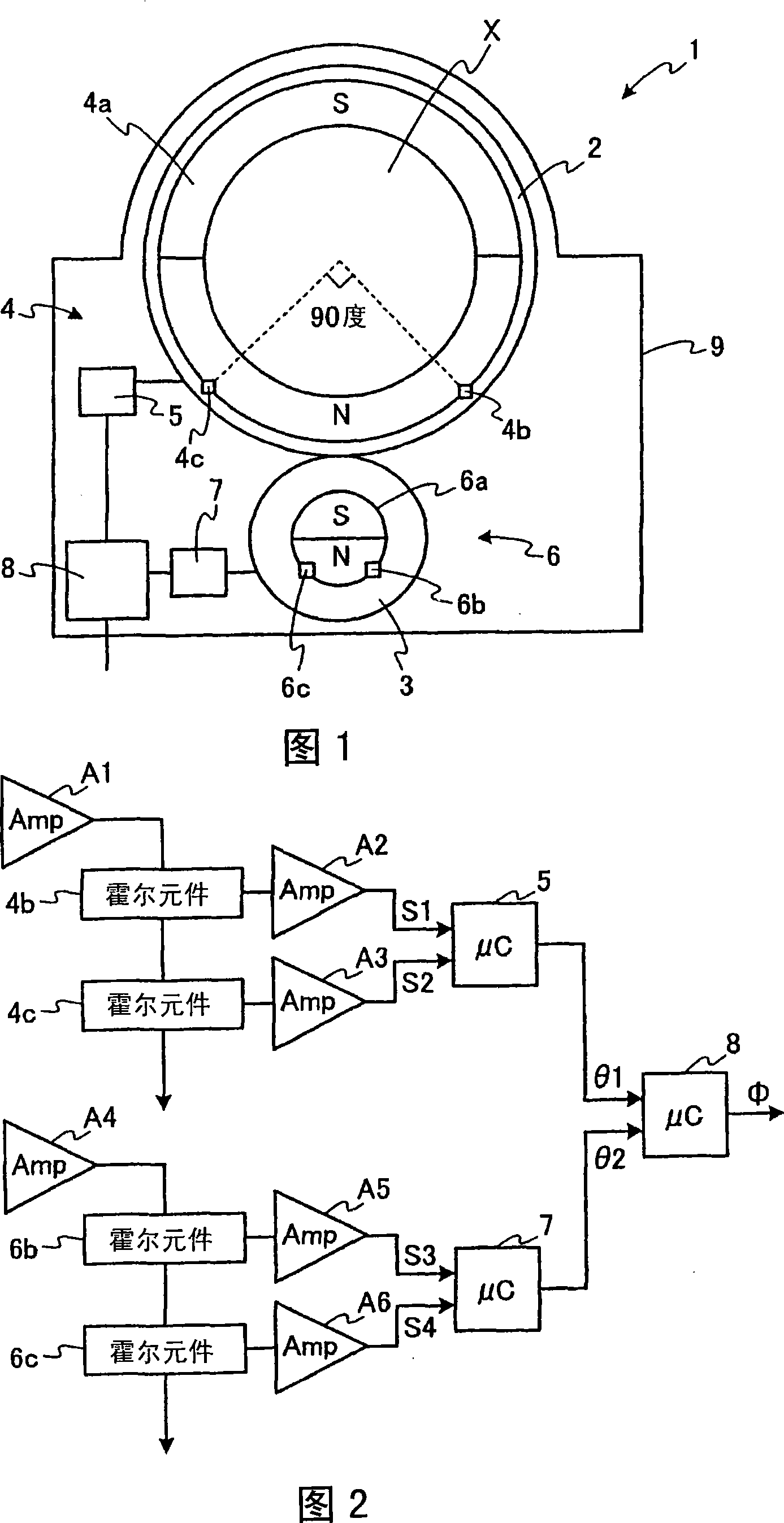
[0067] FIG. 1 is a schematic cross-sectional view schematically showing a rotation angle detection device according to Embodiment 1 of the present invention. The rotation angle detection device according to Embodiment 1 detects the rotation angle of a steering shaft of an automobile as a rotating body to be detected.
[0068] In addition, the rotation angle detecting device according to Embodiment 1 is an example in which the above-mentioned signals (A) to (D)
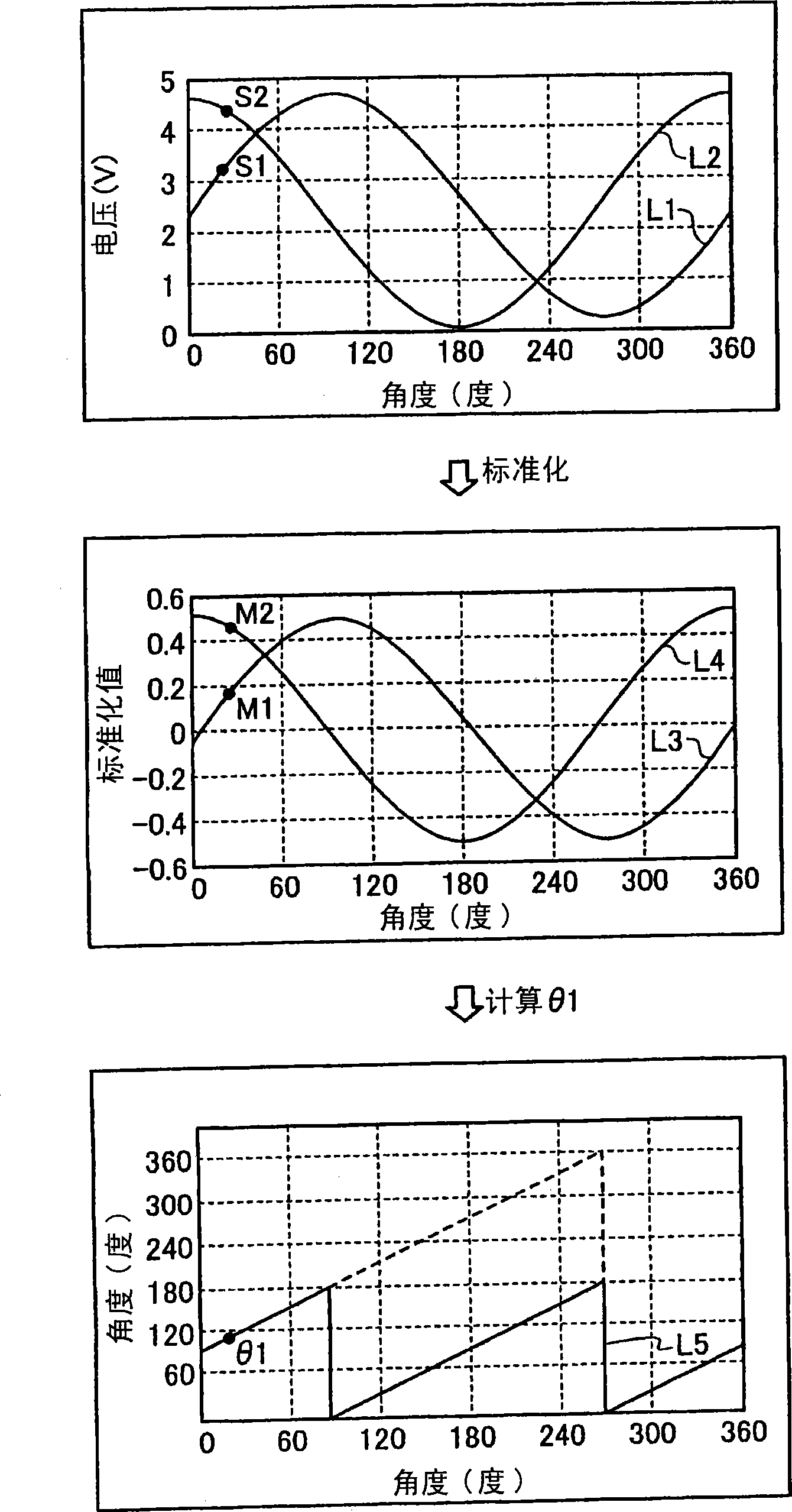
[0069] (C) Input signal from the main rotation detection mechanism processed in the signal processing mechanism
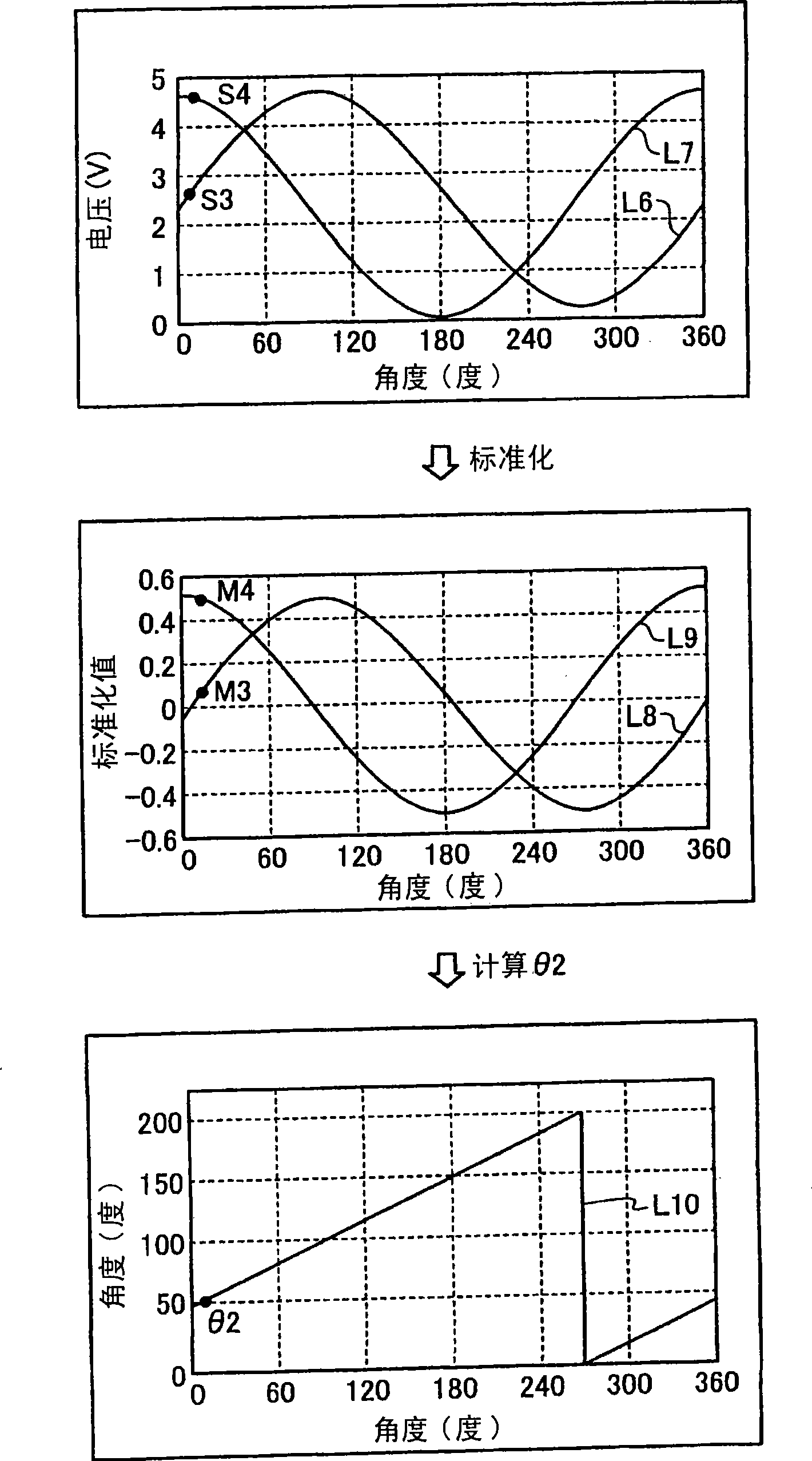
[0070] (D) The period of the input signal signal from the sub-rotation detection mechanism processed in the signal processing mechanism is set to be different from the period of one revolution of the main or sub-rotation body.
[0071] As shown in FIG. 1 , the rotation angle detecting device 1 includes: a ring-shaped main gear 2 as a main rotating body, which is installed and fixed by inserting a steering ...
Embodiment approach 2
[0126] Figure 8 It is a schematic cross-sectional view schematically showing a rotation angle detection device according to Embodiment 2 of the present invention. The rotation angle detection device of the second embodiment detects the rotation angle of the steering shaft of the automobile as the rotating body to be detected, as in the first embodiment.
[0127] In addition, the rotation angle detecting device according to Embodiment 2 is an example in which, among the above-mentioned (A) to (D) signals,
[0128] (A) Output signal of the main rotation detection mechanism
[0129] (B) Output signal of sub-rotation detection mechanism
[0130] The period of at least one of the signals is set to be different from the period of one revolution of the main rotator or the auxiliary rotator.
[0131] Such as Figure 8 As shown, the rotation angle detection device 101 includes: the ring-shaped main gear 102 as the main rotating body, which is installed and fixed by inserting the s...
PUM
 Abstract
Description
Claims
Application Information