Loop control method for wire tandem rolling and device

A control method and looper technology, applied in rolling mill control devices, metal rolling, metal rolling, etc., can solve problems affecting steel bite, steel material scrapping, large overshoot, etc., achieve simple structure, improve steel bite The effect of success rate and ease of use

Inactive Publication Date: 2009-07-01
SHENYANG INST OF AUTOMATION - CHINESE ACAD OF SCI
View PDF0 Cites 23 Cited by
  • Summary
  • Abstract
  • Description
  • Claims
  • Application Information

AI Technical Summary

Problems solved by technology

In the previous looper control method, a large overshoot often occurred in the process of setting up the looper, which affected the normal biting of the steel and made the entire piece of steel scrap

Method used


Image

  • Loop control method for wire tandem rolling and device
  • Loop control method for wire tandem rolling and device
  • Loop control method for wire tandem rolling and device

Examples


Embodiment Construction

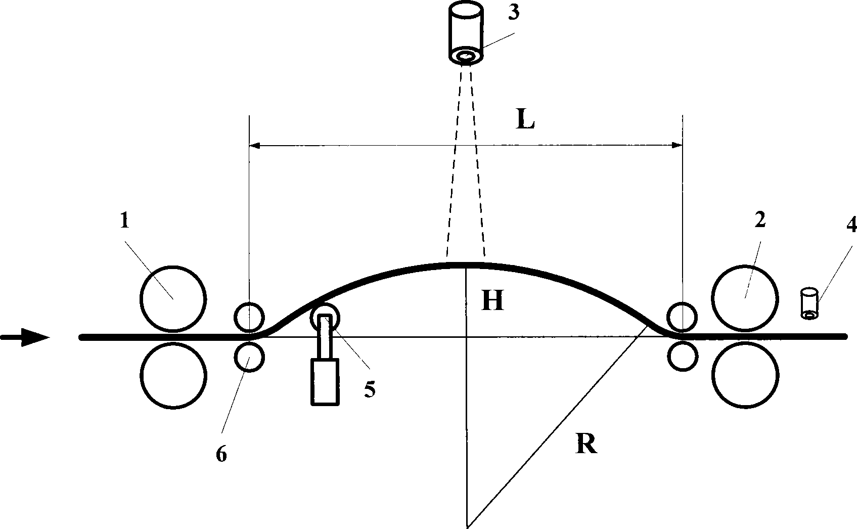
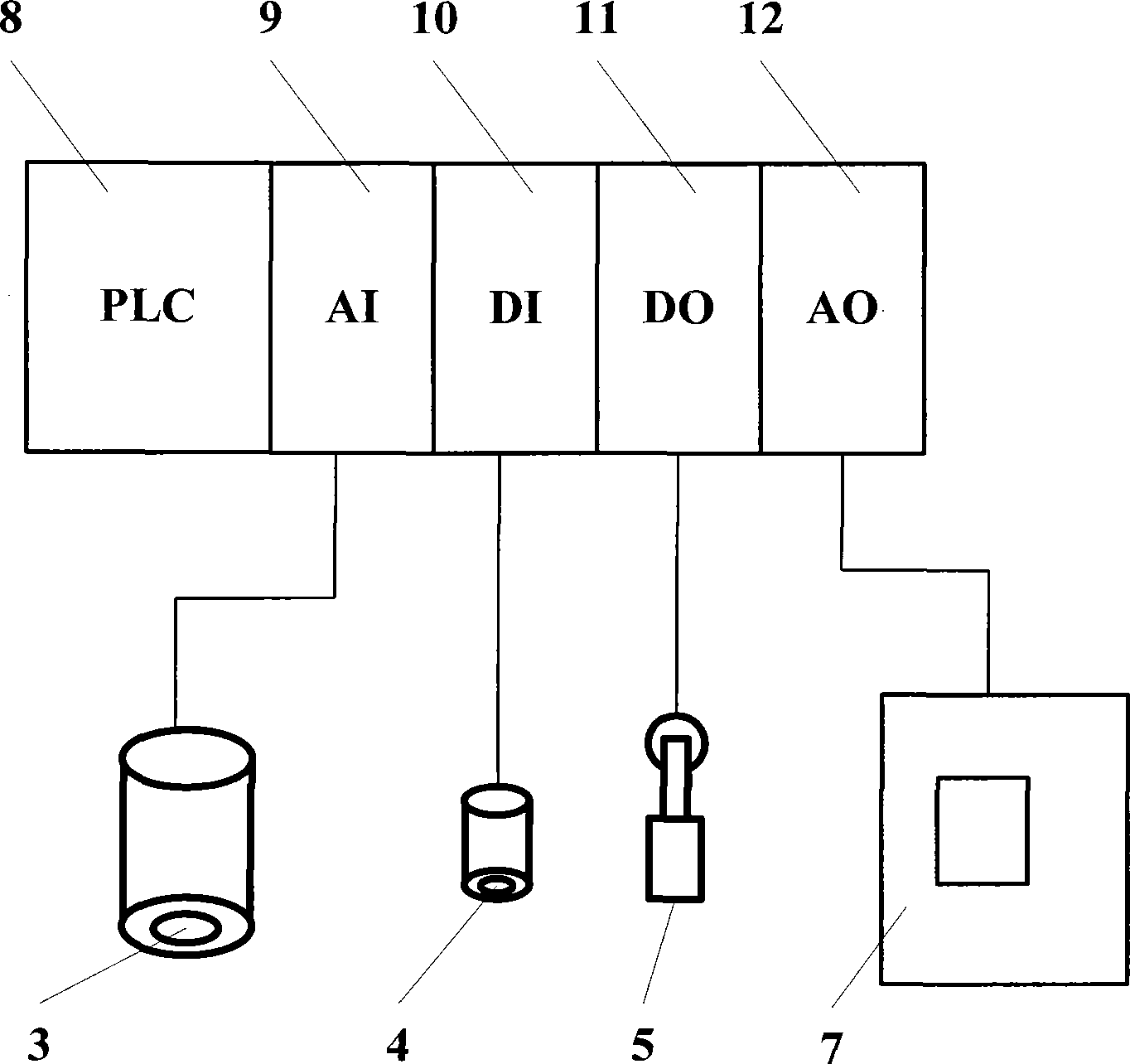
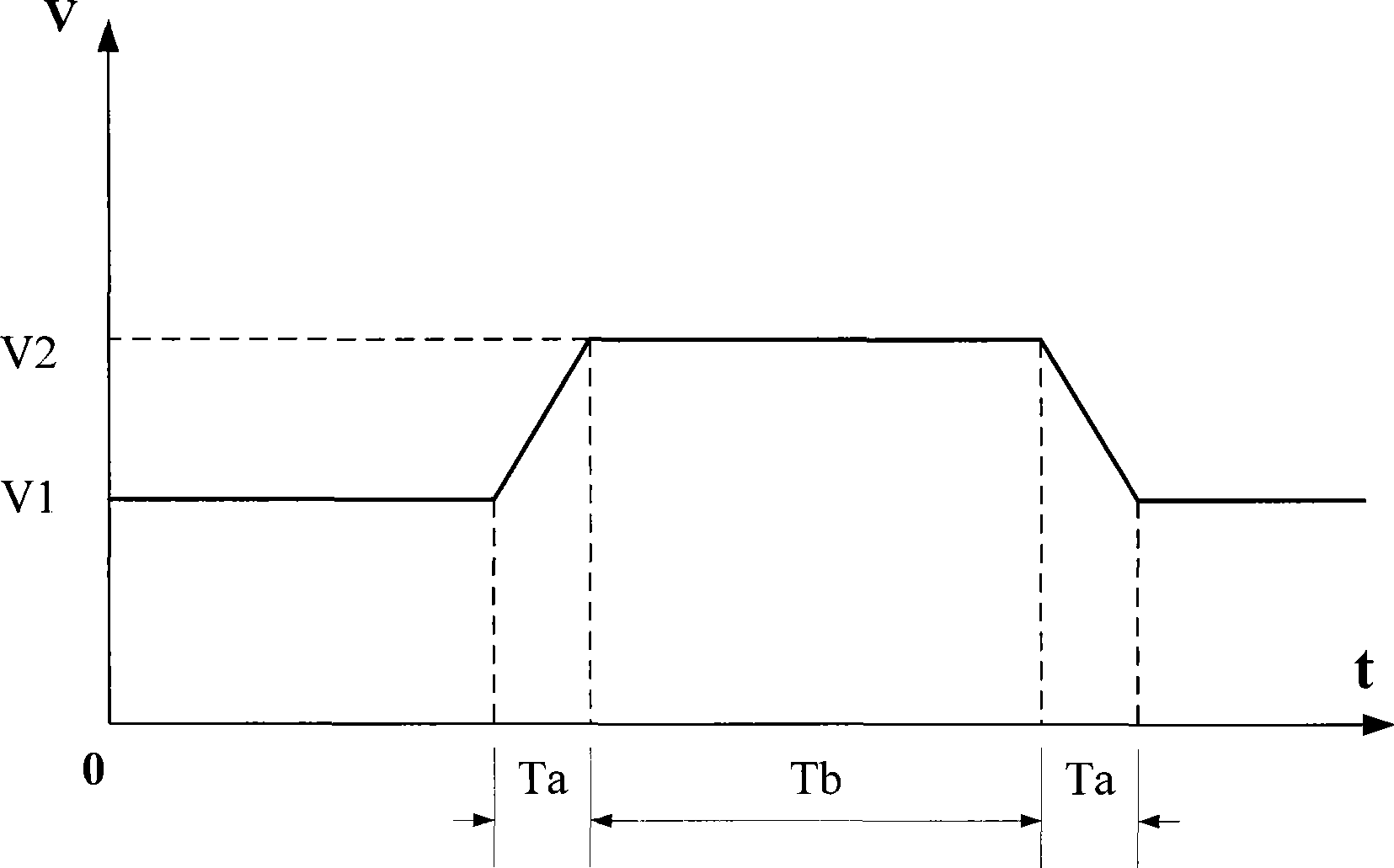
[0019] The control method of the present invention: use the guide wheel 6 located between two adjacent rolling mills to guide the wire into the rolling mill, the sheathing sensor 4 installed at the exit of the second rolling mill 2 detects the arrival signal of the head of the wire rod and issues a sheathing command, through the sheathing The auxiliary cylinder 5 is used to start the sleeve smoothly, and the programmable controller 8 is used to adjust the speed of the rolling mill according to the calculated rolling mill speed-up curve parameters and to control the extension of the auxiliary cylinder 5 to perform the sleeve start; after the sleeve start is completed, the closed-loop PID digital control Algorithms adjust the speed of the rolling mill to control the height of the looper. Since the actual height of the looper is equal to or close to the set looper height during closed-loop PID control, the overshoot of the looper control is very small, thereby effectively improvin...


PUM


Abstract

The invention discloses a method and a device for controlling a movable sleeve for the continuous rolling of a wire material. The method comprises: a guide wheel positioned between two adjacent rolling machines conducts the wire material to a rolling machine; a sleeve removing sensor arranged in an outlet of the rolling machine detects a reaching signal in the head of the wire material and emits a sleeve removing command; the sleeve is removed through a sleeve removing auxiliary cylinder; a programmable controller is adopted to adjust the speed of the rolling machine and control the stretching of the sleeve removing auxiliary cylinder for carrying out the sleeve removing according to calculated raising speed curve parameters of the rolling machine; and through a closed-loop PID digital control algorithm, the speed of the rolling machine is adjusted to control the height of the movable sleeve. The device comprises a first rolling machine, a second rolling machine, a movable sleeve scanner, a sleeve removing sensor, an auxiliary cylinder, and guide wheels; the movable sleeve scanner is positioned on the highest point of removing the movable sleeve between the first rolling machine and the second rolling machine; the sleeve removing sensor is arranged in the outlet end of the second rolling machine; the sleeve removing auxiliary cylinder is positioned in the outlet end of the first rolling machine; and the positions between the first rolling machine and the second rolling machine respectively close to the rolling machines are provided with the guide wheels. The device has the characteristics of simple structure, convenient use, and the like.

Description

technical field [0001] The invention relates to the continuous rolling technology of wire rods, in particular to a looper control method and device for continuous rolling of wire rods which can effectively reduce the overshoot of looper opening. Background technique [0002] The production process of the continuous rolling production line is as follows: After the steel billet is heated to 1100 degrees by the heating furnace, it is rolled by more than 10 rolling mills successively through rough rolling, intermediate rolling, and finishing rolling to become a finished wire rod. In order to avoid affecting the quality of the wire rod due to drawing steel between two adjacent stands during the rolling process, a looper device is usually installed between each finish rolling stand. In the previous looper control method, a large overshoot often occurred during the looping process, which affected the normal steel biting and made the entire steel material scrapped. Contents of the...

Claims


Application Information

Patent Timeline
Patent Type & Authority Applications(China)
IPC IPC(8): B21B37/00B21B41/12B21B1/18G05B19/05
Inventor 朱军荣胜波吴景辉史勃
Owner SHENYANG INST OF AUTOMATION - CHINESE ACAD OF SCI
Why Eureka
Try Eureka