

Sliding table for cutting machine
A cutting machine and table top technology, applied in metal sawing equipment, metal processing machinery parts, large fixed members, etc., can solve problems such as reducing workability or cutting accuracy, affecting workability, etc., to achieve reasonable structure, good workability, The effect of good cutting accuracy
- Summary
- Abstract
- Description
- Claims
- Application Information
AI Technical Summary
Problems solved by technology
Method used
Image

Examples
Embodiment approach 1
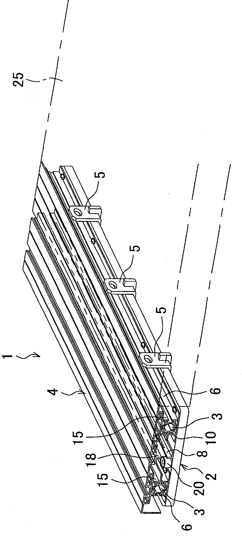
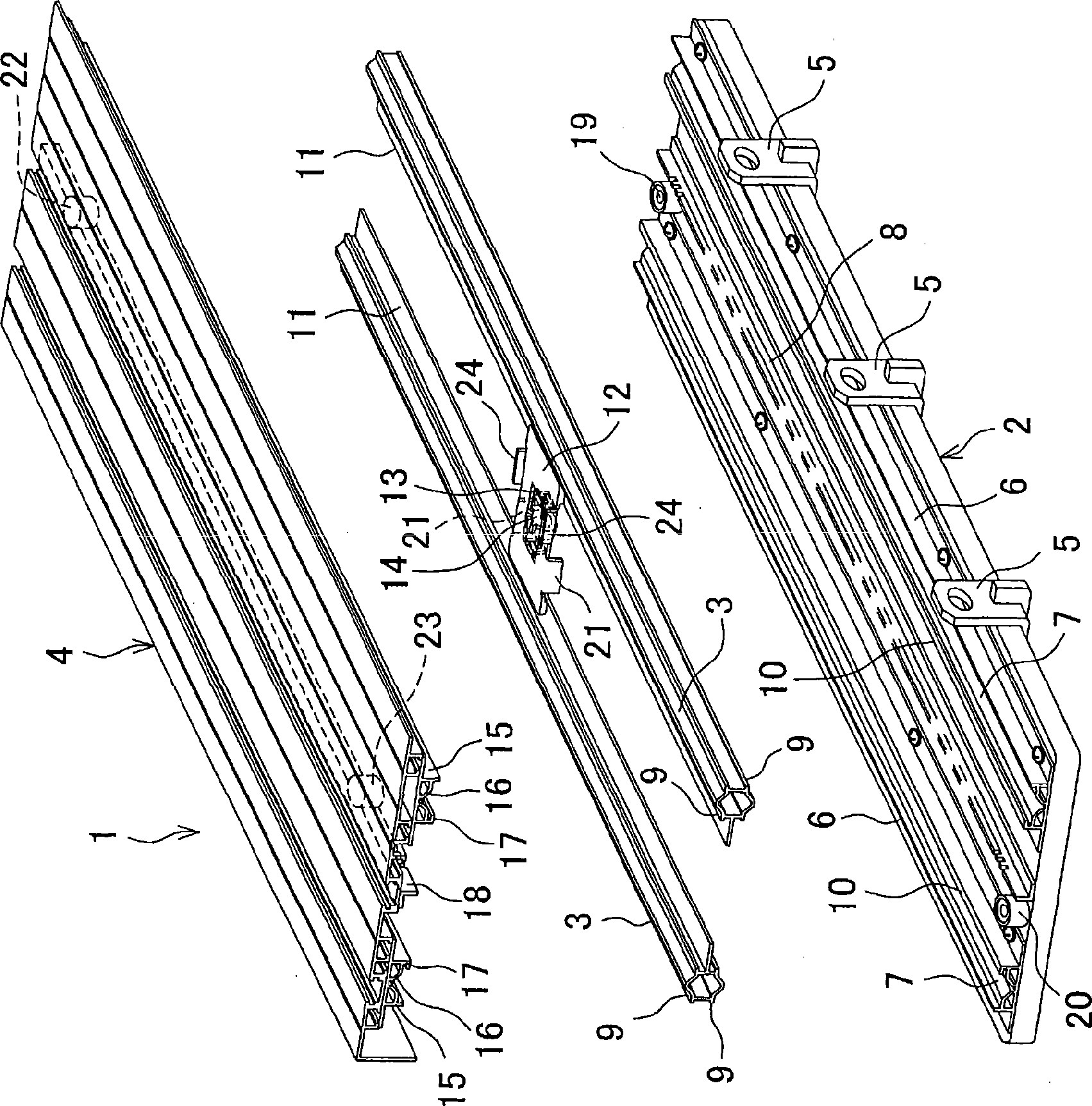
[0031] figure 1 is a perspective view of a sliding table, figure 2 Yes figure 1 An exploded perspective view of a sliding table. The sliding table top 1 comprises: a rectangular base plate 2, which is connected to the side edge of the table top 25 of a cutting machine such as a table saw; a pair of parallel rails 3,3, which are arranged on the base plate 2, and whose long sides are slightly shorter than The length of the long side of the bottom plate 2, and can slide relative to the bottom plate 2 along the long side direction; the panel 4, whose shape is roughly the same as the bottom plate 2, is arranged on the rails 3, 3 and can slide relative to the rails 3, 3 in the long side direction .
[0032] On one long side of the bottom plate 2, several connecting pieces 5 (three in this embodiment) are fixed at predetermined intervals for connecting the bottom plate 2 to the table top 25 of the table saw. A pair of parallel lower guide rails 6,6 are installed on the upper sur...
Embodiment approach 2
[0048] Components in the second embodiment that are the same as those in the first embodiment described above are denoted by the same reference numerals and repeated description thereof will be omitted.
[0049] In this embodiment, a pulley-rope structure is adopted. In other words, in Figure 4 In the shown sliding platform 1a, on the one hand, a rotatable first pulley 30 (running wheel) is fixed on the front end inner side of the left track 3 (the side near the center of the sliding panel is the inner side, the same below), and on the right side of the track 3 The rear end inner side is fixed with the rotatable 2nd pulley 31 (running wheel), on the other hand, as the 1st rope 32 of the 1st rope body, its middle part is from the front side of the 1st pulley 30 ( Figure 4 Middle right upper side) is bent around the first pulley 30, the lower end is fixed on the left side of the bottom plate 2 (lower right side in the figure) the rear inner side of the lower guide rail 6, and...
Embodiment approach 3
[0061] Image 6 A perspective view showing a slide panel 1b of another embodiment, Figure 7 yes Image 6 An exploded perspective view of the sliding panel 1b. On one side of the bottom plate 2 along the longitudinal direction, several connecting pieces 5 are fixed at regular intervals for connecting the bottom plate 2 with the table saw panel 140 . exist Figure 8 Also shown in the figure, a pair of parallel lower guide rails 6,6 are installed on the upper surface of the base plate 2, and the two lower guide rails 6,6 have V-shaped grooves 7 that can be fitted with the track 3,3 lower surfaces. Between the lower guide rails 6 and 6, on the lower guide rail 6 side near the left side (with the connecting piece 5 side as the right side and the opposite side as the left side in the figure), near the front and rear end edges of the base plate 2, a The lower stoppers 108, 109 made of rubber material are provided with a protruding upward plate-shaped plate parallel to the lower ...
PUM
 Abstract
Description
Claims
Application Information