Yarn slack eliminating device and spinning machine

A slack elimination device and slack elimination technology, applied in spinning machines, open-end spinning machines, piecing devices, etc., can solve problems such as trouble, inability to make positive changes, and inability to fine-tune resistance torque.

Inactive Publication Date: 2009-07-01
MURATA MASCH LTD
View PDF1 Cites 13 Cited by
  • Summary
  • Abstract
  • Description
  • Claims
  • Application Information

AI Technical Summary

Problems solved by technology

However, this structure requires adjustment of the yarn slack eliminating device for each spindle when changing the resistance torque of multiple spindles at the same time, such as changing the processing type, which is very troub

Method used


Image

  • Yarn slack eliminating device and spinning machine
  • Yarn slack eliminating device and spinning machine
  • Yarn slack eliminating device and spinning machine

Examples


Embodiment Construction

[0033] Next, a spinning frame (spinning machine) according to an embodiment of the present invention will be described with reference to the drawings. In addition, "upstream" and "downstream" in this specification refer to upstream and downstream in the yarn traveling direction during spinning.

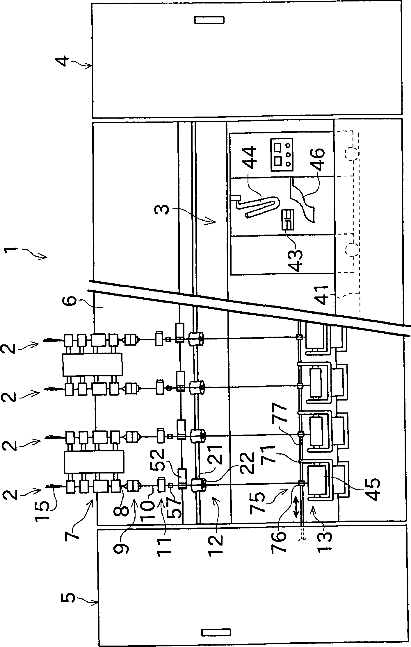
[0034] as figure 1 The spinning frame 1 of the illustrated spinning machine has a plurality of spindles (spinning units 2 ) arranged side by side. The spinning frame 1 includes a piecing cart 3 , a blower case 4 and a prime mover case 5 . The piecing cart 3 is movable in the direction in which the spinning units 2 are arranged.

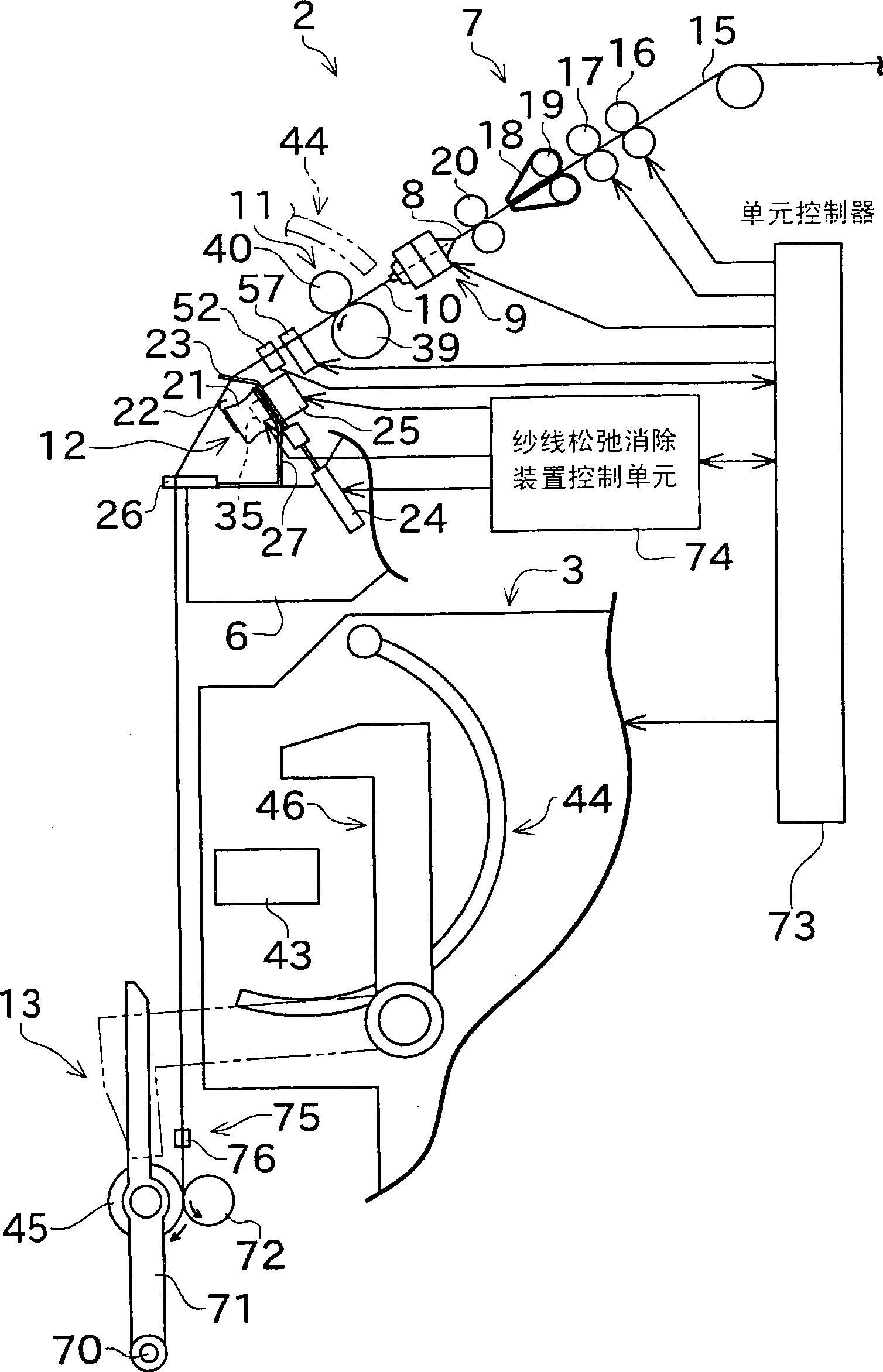
[0035] Such as figure 1 As shown, each spinning unit 2 has a drafting device 7, a spinning device 9, a yarn feeding device 11, a yarn slack eliminating device 12 and a winding device 13 as main structures from upstream to downstream. The draft device 7 is provided near the upper end of the frame body 6 of the spinning frame 1 . The fiber bundle 8 conveye...


PUM


Abstract

An object of the present invention is to provide a yarn slack eliminating device that enables tension applied to a yarn to be controlled while a spinning machine is in operation. A yarn slack eliminating device 12 includes an electric motor 25, a yarn slack eliminating roller 21, a yarn hooking member 22, an electromagnet 36, and a control section 74. The yarn slack eliminating roller 21 is rotationally driven by the electric motor 25. The yarn hooking member 22 is concentrically attached to the yarn slack eliminating roller 21 so as to be rotatable relative to the yarn slack eliminating roller 21. The electromagnet 36 generates a magnetic field to be applied to the yarn hooking member 22. The control section allows the magnetic field to generate a resistance torque resisting the rotation of the yarn hooking member 22 relative to the yarn slack eliminating roller 21. The control section 74 also controls an input to the electromagnet 36 to control the resistance torque.

Description

technical field [0001] The present invention relates to a yarn slack eliminating device for eliminating yarn slack generated during the period from spinning out yarn to winding up into a package in a spinning machine. Furthermore, the present invention also relates to a spinning machine provided with the above-mentioned yarn slack eliminating device. Background technique [0002] In the past, high-speed spinning machines such as air-type spinning machines that wind spun yarns to form packages have adopted such a structure that when a yarn defect is detected, the yarn defect is cut off with a yarn cutter and removed. Remove, and the yarn end of the yarn that is constantly sent from the spinning device is joined with the yarn end of the package side with a jointing device. Since the above-mentioned piecing operation is performed in a state where yarn winding is stopped, it is necessary to eliminate yarn slack. [0003] In view of this situation, Japanese Patent Application L...

Claims


Application Information

Patent Timeline
IPC IPC(8): D01H13/10D01H13/14D01H15/00B65H59/00B65H63/00
CPCD01H13/104B65H2701/31B65H51/22D01H13/10D01H4/48
Inventor 马场健治
Owner MURATA MASCH LTD
Why Eureka
Try Eureka