Method, system and apparatus for fault detection of tested device

A fault detection and tested technology, applied in the communication field, to achieve the effect of improving fault isolation rate, increasing bus speed, and facilitating maintenance

Inactive Publication Date: 2009-07-01
HUAWEI TECH CO LTD
View PDF0 Cites 4 Cited by
  • Summary
  • Abstract
  • Description
  • Claims
  • Application Information

AI Technical Summary

Problems solved by technology

Simultaneously increase the bus speed

Method used


Image

  • Method, system and apparatus for fault detection of tested device
  • Method, system and apparatus for fault detection of tested device
  • Method, system and apparatus for fault detection of tested device

Examples


Embodiment Construction

[0034] The embodiments of the present invention will be further described below in conjunction with the drawings and examples.

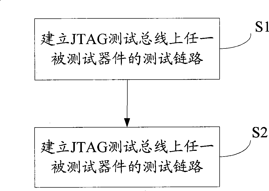
[0035] Embodiment 1 of the present invention provides a method for fault detection of a device under test, such as figure 2 shown, including:

[0036] S1, establishing a test link of any device under test on the JTAG test bus.

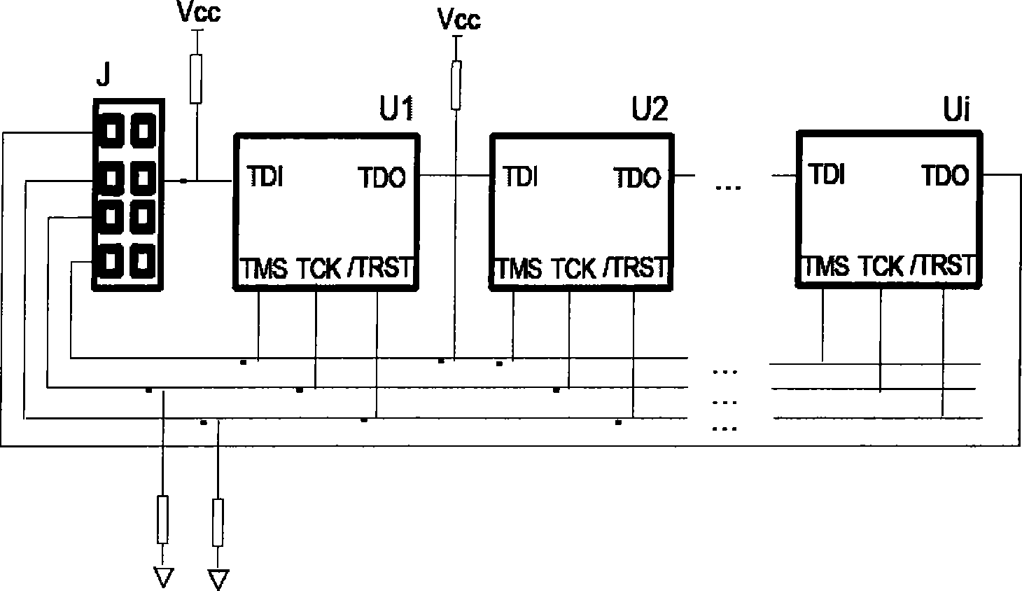
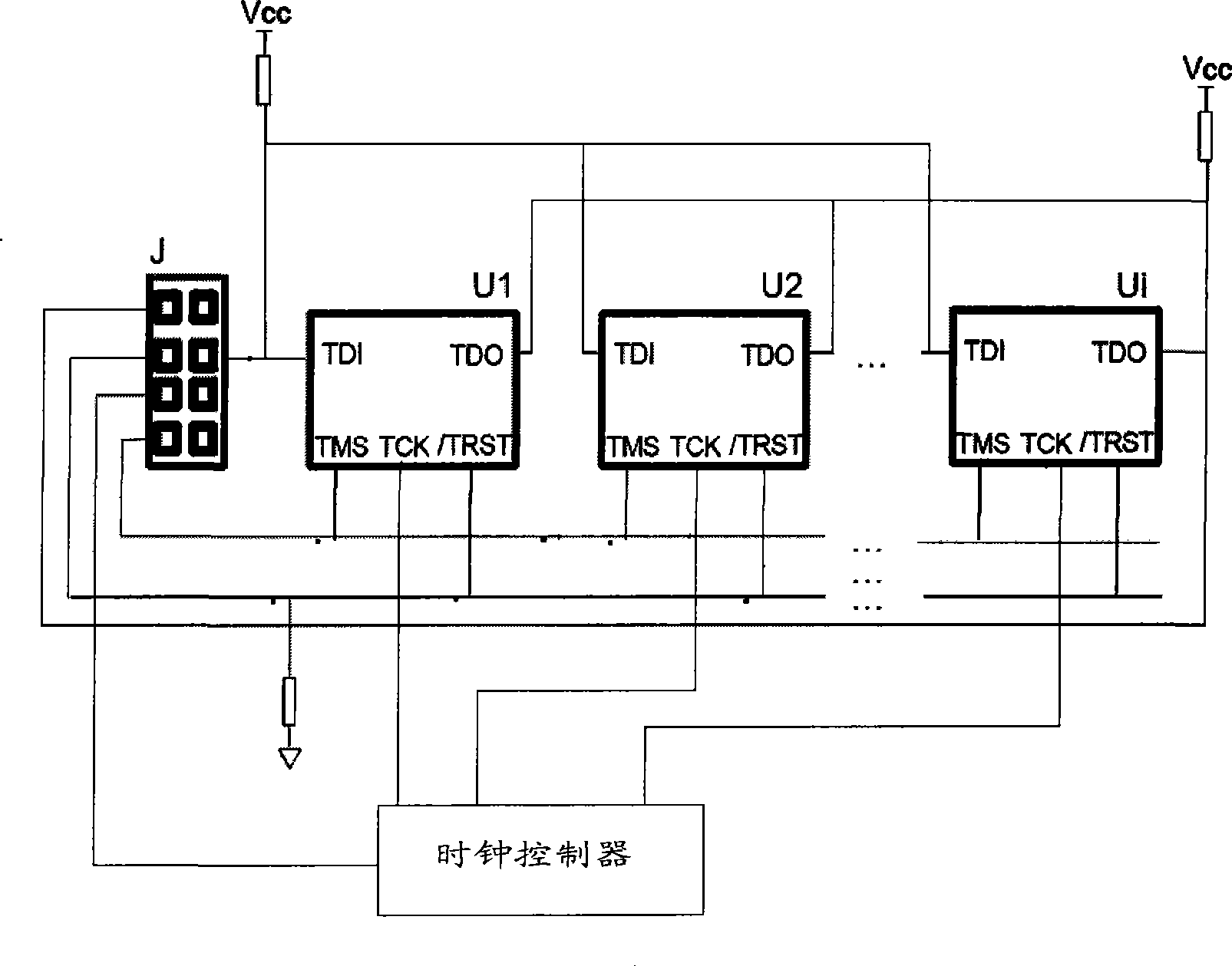
[0037] In S1: the JTAG controller controls the clock controller to gate the device under test, the JTAG controller and the clock controller, and the device under test establish a point-to-point drive simultaneously, and establish any device under test and JTAG test Bus test link, output clock. Wherein, the device under test is connected to the JTAG test bus in parallel. Wherein the clock controller performs timing analysis on the JTAG test bus through programmable logic analysis to accurately estimate the clock delay.

[0038] S2. Test the device under test, and if the data returned to the JTAG controller is abnormal or ...


PUM


Abstract

The invention discloses a method for inspecting the faults of object devices, a system and a device therefore. The method comprises: establishing a test link between one object device and a JATG test bus; testing the object device, and if the data feedback to the JATG controller is abnormal or there is not data received, considering that the object device has faults. The method can improve fault isolation rate, thus being convenient for maintenance, and can improve bus speed and bus reliability.

Description

technical field [0001] The invention relates to the field of communication technology, in particular to a method, system and device for fault detection of a device under test. Background technique [0002] At present, the JTAG bus is widely used for testing single-board interconnection and loading logic devices. The bus hardware structure is as figure 1 shown. [0003] J in the figure represents the JTAG socket for off-line loading and testing of the board. If the board needs to support online loading (upgrade) and testing, a JTAG controller can be used to connect to J. [0004] The JTAG test port that complies with IEEE STD (Institute of Electrical and Electronics Engineering Standard, American Institute of Electrical and Electronics Engineers Standard) 1149.1 is an online emulation port reserved by chip manufacturers for developers, and it is also an application of edge scan test technology . [0005] The basic idea of ​​edge-scan testing is to add a shift register uni...

Claims


Application Information

Patent Timeline
IPC IPC(8): G01R31/3185
Inventor 高岩
Owner HUAWEI TECH CO LTD
Why Eureka
Try Eureka