
Radiating device

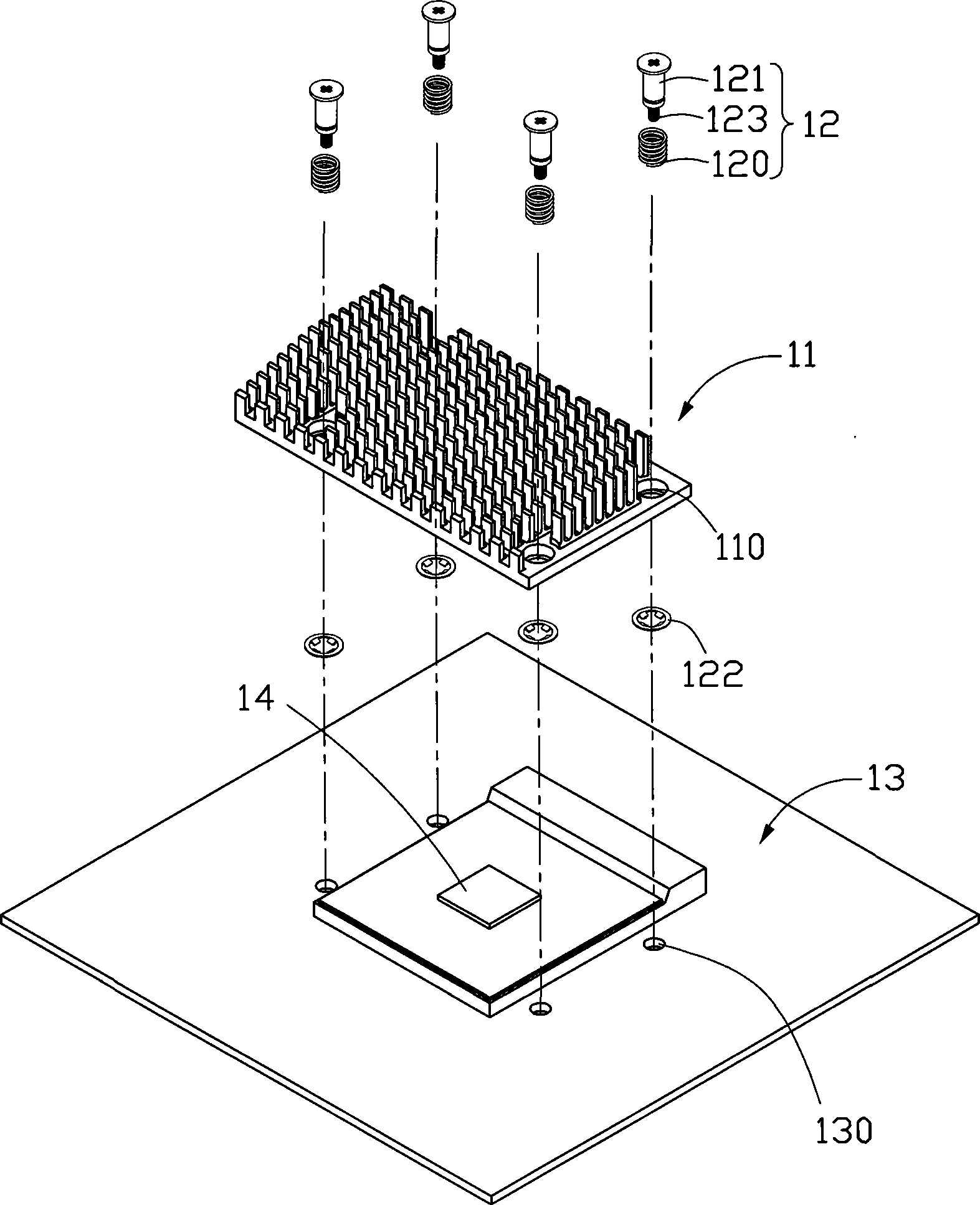
A technology of a heat sink and a heat sink group, which is applied in cooling/ventilation/heating transformation, electrical components, electrical solid devices, etc., can solve the problem of increasing material cost and manufacturing cost, short circuit of circuit board, and loose buckle 122, etc. problems, to reduce assembly and material costs, and eliminate circuit board shorts

Inactive Publication Date: 2009-07-01
FU ZHUN PRECISION IND SHENZHEN +1
View PDF0 Cites 7 Cited by
  • Summary
  • Abstract
  • Description
  • Claims
  • Application Information

AI Technical Summary

Problems solved by technology

[0003] Since the radiator 11 is installed, the buckle 122 cannot play any role, which increases the material cost and manufacturing cost, and may cause the buckle of the buckle 122 to be loose due to improper assembly, especially when the buckle 122 is made of metal. If it falls off, it will cause a short circuit hazard to the circuit board

Method used


Image

  • Radiating device
  • Radiating device
  • Radiating device

Examples


Embodiment Construction

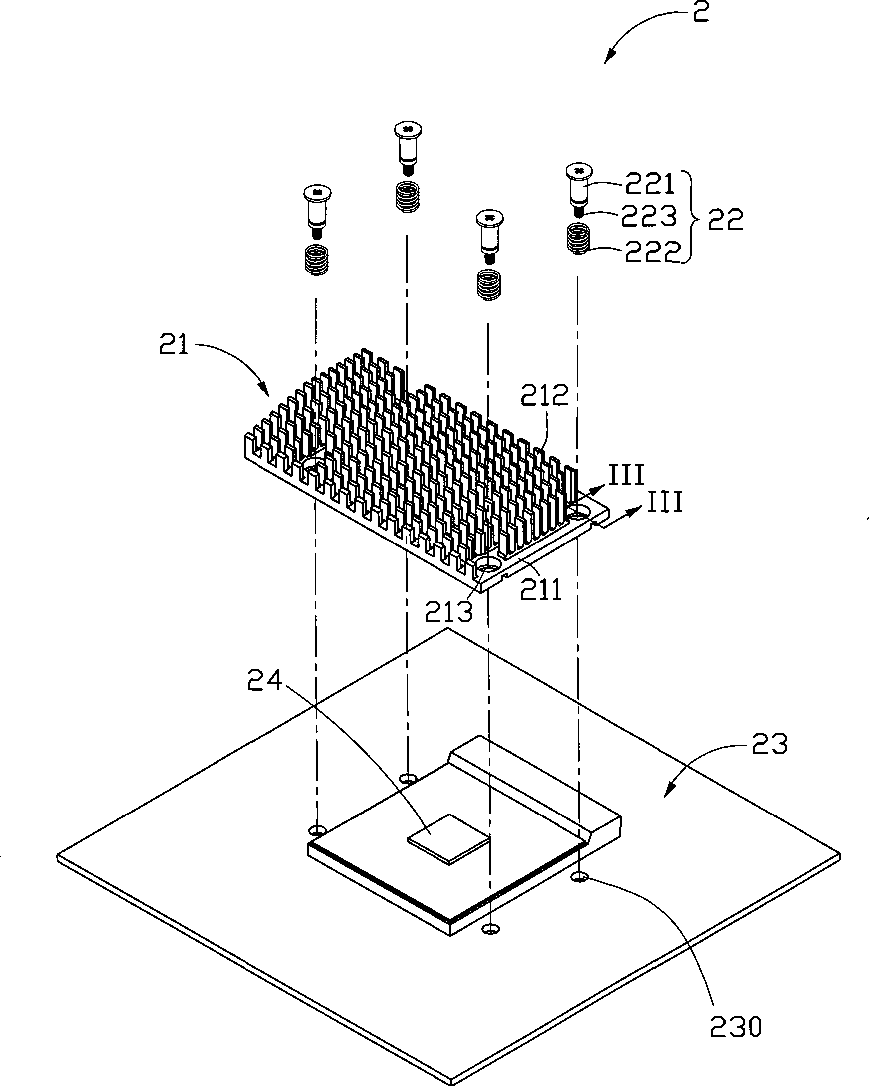
[0014] The heat dissipation device will be further described below with reference to the accompanying drawings. Such as figure 2 , 3 , 4, the cooling device 2 includes a radiator 21, a number of spring fasteners 22, a circuit board 23 and a heating electronic component 24 mounted on the circuit board 23.

[0015] The spring fastener 22 includes a fastener 221 and a spring 222 . The spring 222 is sheathed on the fastener 221 . In this embodiment, the spring fastener 22 is a spring screw with a thread 223 at its bottom. The fastener 221 forms a threaded connection with the threaded hole 230 on the circuit board 23 . In order to firmly cover the spring 222 on the fastener 221, an annular protrusion 2212 protrudes from the outer surface near the top of the fastener 221, and a groove 2211 is formed between the top of the fastener 221 and the annular protrusion 2212, and the spring 222 The top ring 2221 is set in the groove 2211. When the spring fastener 22 is installed, due to...


PUM


Abstract

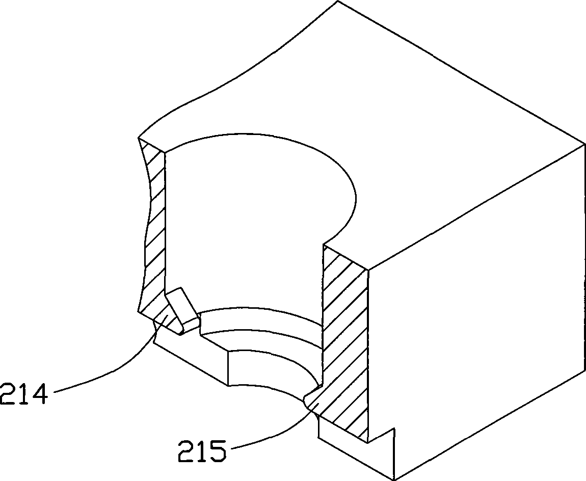
A heat sink includes a base and at least one spring retainer. A spring is sleeved on the spring retainer; a through hole allowing the spring retainer to pass through is formed on the base; a buckle is arranged in the through hole or nearby the through hole on the base; and the buckle clips at least one spring ring of the spring between the base and the buckle. Compared with the prior art, the invention uses the buckle on the base to replace a retaining ring, reduces cost for retaining ring assembly and materials, and eliminates risk of short-circuited circuit board caused by retaining ring falling off.

Description

technical field [0001] The invention relates to a heat dissipation device, in particular to a heat dissipation device for heating electronic components. Background technique [0002] At present, with the rapid development of the computer industry, more and more heat is generated by heat-generating electronic components such as micro-processing chips. Such as figure 1 As shown, in order to dissipate the excess heat effectively, the existing method is to attach a heat sink 11 on the surface of the heating electronic component 14, dissipate the heat generated by the heating electronic component 14, and utilize the spring screw 12 to dissipate the heat sink 11 is fixed on the circuit board 13, and the spring screw 12 refers to the assembly formed by the spring 120 sleeved on the screw 121. The radiator 11 is provided with a plurality of through holes 110 . The outer diameter of the spring 120 is larger than the diameter of the through hole 110 , and the diameter of the thread...

Claims


Application Information

Patent Timeline
IPC IPC(8): H05K7/20H01L23/40
Inventor 谢宜莳乔鹏
Owner FU ZHUN PRECISION IND SHENZHEN
Learn More