
RH dry type vacuum refining apparatus

A technology of vacuum refining and vacuuming device, applied in the field of RH dry vacuum refining device, can solve the problems of reducing the failure rate of the device, affecting the refining effect, and high failure rate of the vacuum device, so as to reduce the failure rate of the device and ensure long-term operation. , Eliminate the effect of high energy consumption

Active Publication Date: 2009-07-08
DESIGN INST OF CHONGQING IRON & STEEL GRP
View PDF0 Cites 16 Cited by
  • Summary
  • Abstract
  • Description
  • Claims
  • Application Information

AI Technical Summary

Problems solved by technology

However, due to the high energy consumption and water consumption of the steam injection device, and high requirements on steam quality; the investment in auxiliary facilities is high, and there are many supporting auxiliary facilities, such as: fast gas boilers, gas supply facilities, steam condensers, boiler feed water Purification devices and sewage treatment facilities, etc., have many auxiliary equipment, so there are many factors that affect the operation of vacuum devices, such as high failure rate, which in turn affects the effect of large-scale continuous refining of molten steel outside the furnace
[0004] Therefore, there is a need for a RH vacuum refining device that can obtain the high vacuum required for molten steel refining, eliminate the disadvantages of high energy consumption and high water consumption of existing steam injection devices, save costs, simplify the setting of auxiliary equipment, and reduce the cost of the device. The failure rate ensures the long-term operation of the RH vacuum refining device and the refining effect of molten steel outside the furnace

Method used


Image

  • RH dry type vacuum refining apparatus

Examples


Embodiment Construction

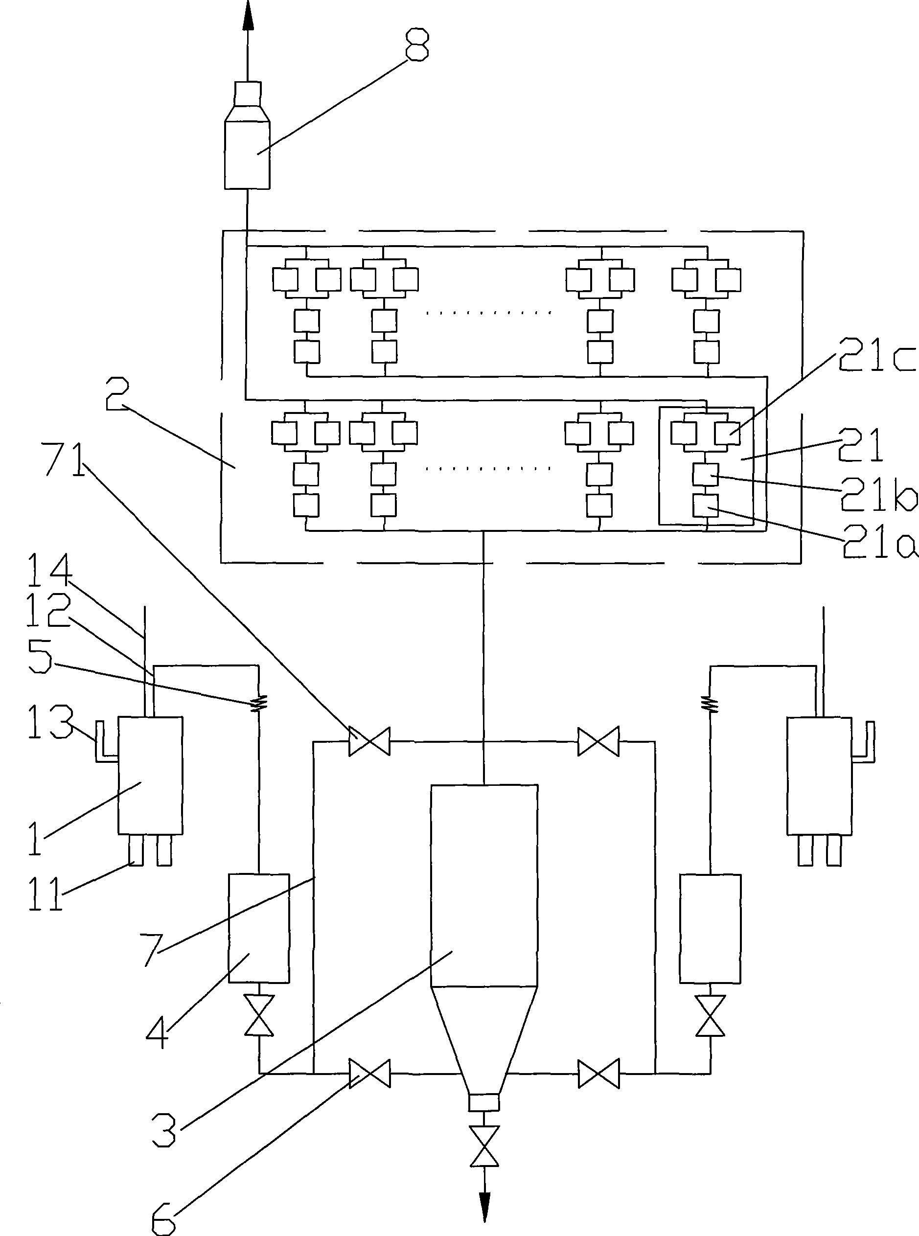
[0018] In the following examples, the RH dry vacuum refining device is a 180T refining device.

[0019] Accompanying drawing is the structure schematic diagram of the present invention, as shown in the figure: the RH dry type vacuum refining device of the present embodiment, comprises vacuum tank 1 and vacuumizing device 2, and described vacuum tank 1 is provided with dip tube 11, hot bend tube 12, Alloy pipeline 13 and oxygen top-blowing gun 14, the inlet of the vacuum pumping device 2 is connected with the hot elbow 12, the vacuum pumping device 2 is a dry vacuum pump device, and the dry vacuum pump device 2 consists of eighteen groups of three-stage Vacuum pump group 21 composed of vacuum pumps, in which the first stage is an IDX1300 double-exhaust screw pump 21a with frequency conversion control, the second stage is a SN7000 mechanical Roots pump 21b, and the third stage is two HV40000 mechanical Roots pump 21c; primary vacuum pump 21a, secondary vacuum pump 21b and tertia...


PUM


Abstract

The invention discloses a RH dry type vacuum refining apparatus comprising a vacuum groove and an evacuating device. The vacuum groove is provided with a varnished tube and a hot-bending tube, the inlet of the evacuating device is communicated with the hot-bending tube, the evacuating device is a dry vacuum pump apparatus. The evacuating device of the invention adopts a dry vacuum pump group, therefore, a high-vacuum degree desired by molten steel refining operation can be obtained, defects that the energy-consumption and water-consumption of the existing steam jet apparatuses are high are overcome, the cost is saved, the setting of auxiliary assemblies is simplified, furthermore, the failure rate of the apparatus is reduced, and a long period operation of the RH vacuum refining apparatus and an effect of external refining of molten steel can be both guaranteed. The RH dry type vacuum refining apparatus which solves the technical problem in the replacing of a steam jet device by a dry type vacuum device for many years at home and abroad has an energy-consumption which is one thirteenth of that of a steam jet pump group and a water-consumption which is one tenth of that of a steam jet pump group.

Description

technical field [0001] The invention relates to a molten steel secondary refining device for producing high-quality steel, in particular to an RH dry vacuum refining device. Background technique [0002] The RH vacuum treatment process is a secondary refining process for molten steel used to produce high-quality steel. In the whole process, the molten steel metallurgical reaction is carried out in a vacuum tank lined with refractory lining. The lower part of the vacuum tank is two dipping tubes with refractory lining, and the upper part is equipped with a hot bend pipe. The pumped gas passes through the hot bend pipe. The vacuum device is drawn out and discharged. The RH vacuum treatment process is widely used in the converter process because it adopts the technology of circulating molten steel in the vacuum tank to achieve the advantages of short treatment time, high efficiency, and matching with converter continuous casting. [0003] In the prior art, the vacuuming device...

Claims


Application Information

Patent Timeline
Patent Type & Authority Applications(China)
IPC IPC(8): C21C7/10
Inventor 董荣华周宏李家春杨伟才江洪
Owner DESIGN INST OF CHONGQING IRON & STEEL GRP
Learn More