

Fixed screw rod for plasma cutting machine transformer
A technology of plasma cutting machine and fixing screw, which is applied in the direction of transformer/reactor installation/support/suspension, etc. It can solve the problems of short service life, large loss and low efficiency of the whole machine, and achieve the effect of reducing leakage reactance and improving efficiency
Active Publication Date: 2009-07-08
无锡聚合科创发展有限公司
View PDF0 Cites 0 Cited by
- Summary
- Abstract
- Description
- Claims
- Application Information
AI Technical Summary
Problems solved by technology
In the prior art, iron screws and nuts are usually used to fix the transformer firmly. Since the plasma cutting machine transformer is a transformer with high leakage reactance, the screw made of pure iron has the following problems when fixing: large leakage reactance , large loss, low efficiency, high temperature, and short service life of the whole machine
Method used
View moreImage
Smart ImageViewing Examples

Examples
Embodiment Construction
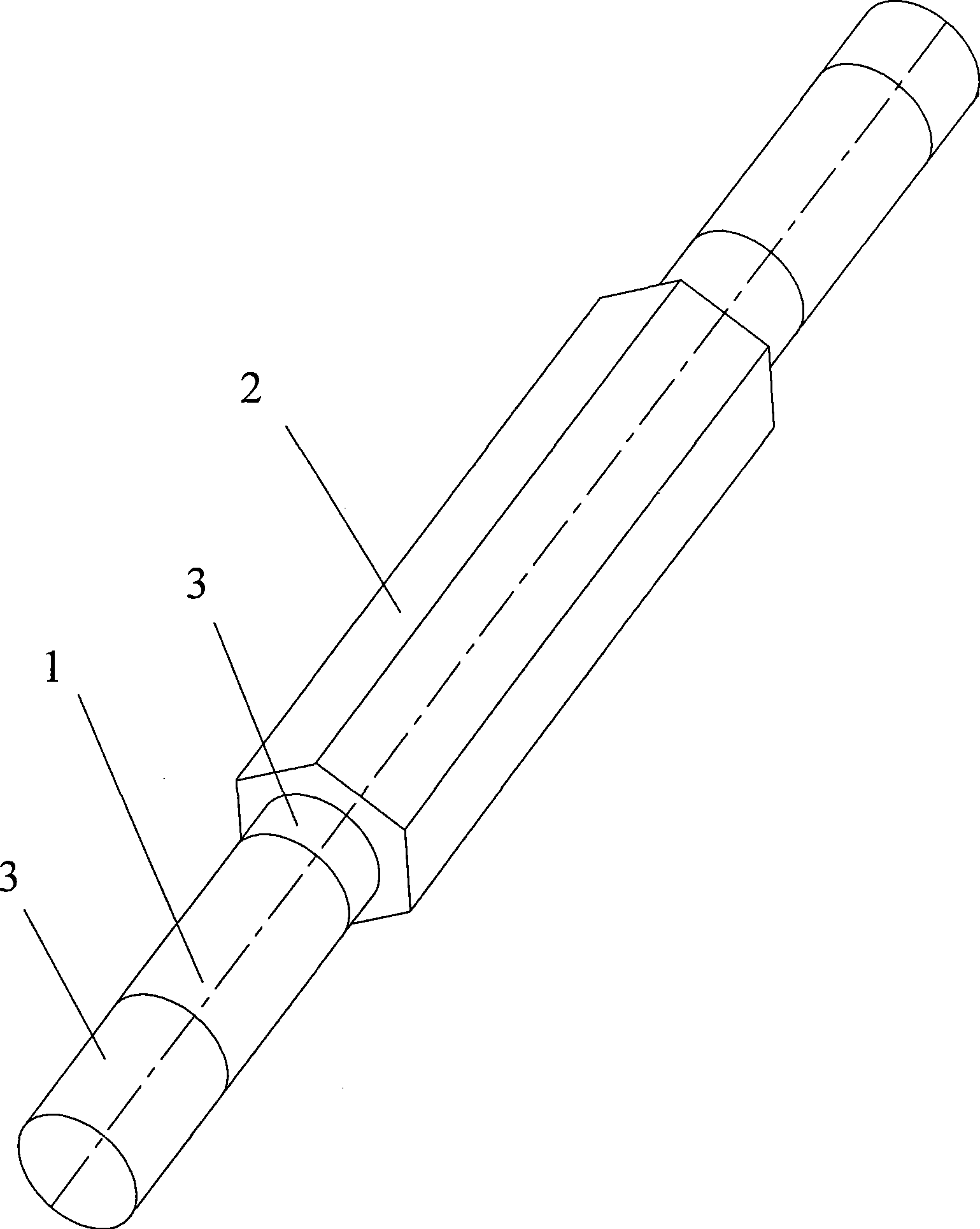
[0010] As shown in the figure: a non-magnetic material layer 2 is provided on the surface of the middle section of the screw body 1 . The two ends are still ordinary iron screws. And external threads 3 are respectively arranged at the middle section and both ends of the screw body 1 .
[0011] The non-magnetic material layer 2 is a copper alloy layer.
[0012] The non-magnetic material layer 2 and the screw 1 are connected to each other by an external thread 3 located in the middle.
[0013] The shape of the non-magnetic material layer 2 is a hollow polygonal cylinder.
[0014] The screw achieves the best match between performance and cost, and has great practicability in high leakage reactance transformers.
Login to View More PUM
 Abstract
The invention relates to a manufacturing technique for a transformer, in particular to a fixed screw rod of the transformer of a plasma cutting machine. According to the invention, a layer of non-permeability magnetic material is arranged on the surface of the middle section of the screw rod, so that a magnetic circuit is interrupted effectively, the leakage reactance is reduced and the efficiency is improved.
Description
technical field [0001] The production technology of the transformer of the present invention is specifically a kind of plasma cutting machine transformer fixing screw. Background technique [0002] When producing a plasma cutting machine transformer, it is necessary to use screws to fix it. In the prior art, iron screws and nuts are usually used to fix the transformer firmly. Since the plasma cutting machine transformer is a transformer with high leakage reactance, the screw made of pure iron has the following problems when fixing: large leakage reactance , large loss, low efficiency, high temperature, and short service life of the whole machine. Contents of the invention [0003] The purpose of the present invention is to design a plasma cutting machine transformer fixing screw, because a layer of non-magnetic material is arranged on the surface of the middle section of the screw, which blocks the magnetic circuit, reduces the leakage reactance, and improves the efficien...
Claims
Login to View More Application Information
Patent Timeline
 Patent Type & AuthorityApplications(China)
IPC IPC(8): H01F27/06
Inventor李明杰
Owner无锡聚合科创发展有限公司