Permanent magnet motor stator multi-phase winding
A technology of permanent magnet motor and phase winding, which is applied to the shape/style/structure of the winding conductor, which can solve the problems of peak power reduction, motor steady-state temperature rise, and poor heat dissipation of the motor, so as to achieve small resistance loss and improve The effect of power factor and convenient voltage adjustment
- Summary
- Abstract
- Description
- Claims
- Application Information
AI Technical Summary
Problems solved by technology
Method used
Image
Examples
Embodiment 1
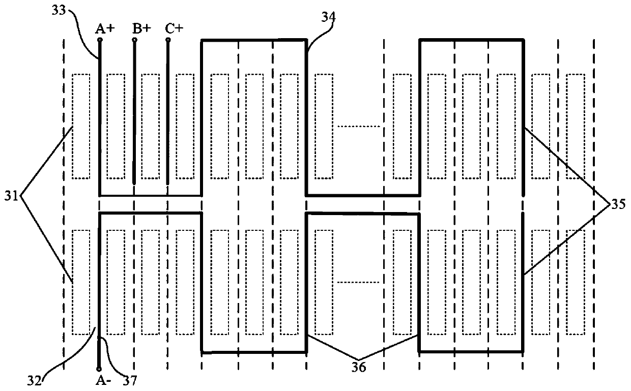
[0039] see Figure 1 to Figure 7 , the multi-phase winding of the stator of the permanent magnet motor, each phase is formed by connecting one coil or multiple coils,
[0040]Each of the coils includes a head-end element and an end element, the head-end element is a double-layer conductor element, the end element is a single-layer conductor element, and there is also a connection between the head-end element and the end element A plurality of double-layer conductor elements; the double-layer conductor element consists of two upper and lower layers of conductors that are respectively covered with an insulating medium, and an interlayer insulating medium can be arranged between the upper and lower layers of outer-insulated conductors as required, and the single-layer The conductor element is composed of a single-layer conductor and an outer insulating dielectric material covering it;
[0041] From the head end element, the upper layer conductors in all double-layer conductor el...
Embodiment 2
[0044] This embodiment is basically the same as Embodiment 1, and the special features are as follows:
[0045] The multi-phase is greater than or equal to 3 phases.
[0046] Each phase consists of multiple coils connected in series or parallel.
[0047] In the double-layer conductor element, each layer of conductor is composed of a single conductor wrapped with an insulating dielectric material.
[0048] In the double-layer conductor element, each layer of conductors, that is, the upper layer conductor or the lower layer conductor, is composed of a single or two parallel conductors wrapped with insulating materials.
[0049] In the terminal element of the single-layer conductor element, the single-layer conductor is composed of a single conductor wrapped with an insulating material.
[0050] In the single-layer conductor element, the single-layer conductor may be composed of two parallel-connected conductors covered with insulating material.
[0051] For the double-layer c...
Embodiment 3
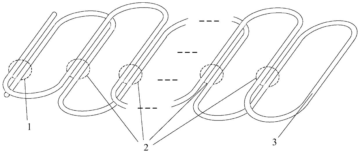
[0053] In this embodiment, a permanent magnet motor stator multi-phase winding, each phase is formed by connecting one coil or multiple coils, wherein each coil is such as figure 1 As shown, it includes a head end element 1 and an end element 3, and several intermediate elements 2 are connected between the head end element 1 and the end element 3. Both the head end element 1 and the middle element 2 are double-layer conductor elements, and the end Element 3 is a single-layer conductor element.
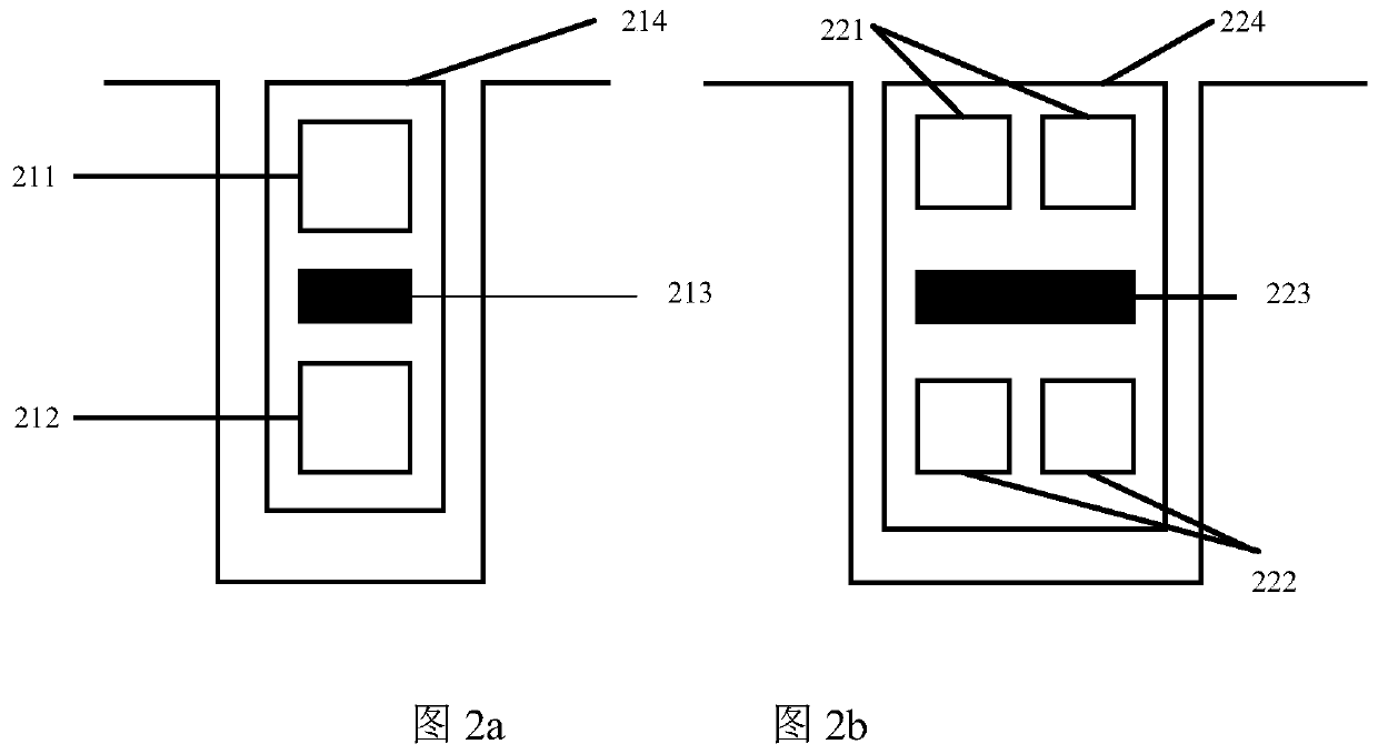
[0054] Wherein, the double-layer conductor element includes a conductor inner core and an outer insulating material covering the inner core, and the inner core is composed of upper and lower layers of conductors and an interlayer insulating dielectric material arranged between the upper and lower layers of conductors. As an example, figure 2 a and figure 2 b shows schematic diagrams of two different structures of the double-layer conductor element.
[0055] figure 2 In a, the do...
PUM
 Abstract
Description
Claims
Application Information
 - R&D
- Intellectual Property
- Life Sciences
- Materials
- Tech Scout
- Unparalleled Data Quality
- Higher Quality Content
- 60% Fewer Hallucinations
Browse by: Latest US Patents, China's latest patents, Technical Efficacy Thesaurus, Application Domain, Technology Topic, Popular Technical Reports.
© 2025 PatSnap. All rights reserved.Legal|Privacy policy|Modern Slavery Act Transparency Statement|Sitemap|About US| Contact US: help@patsnap.com


