Winding, stator and motor

A winding and stator technology, applied in the shape/style/structure of motors, winding conductors, electromechanical devices, etc., can solve the problems of high cost, reduce motor efficiency and density, and improve electrical load density and achieve high density. , the effect of loss reduction

Pending Publication Date: 2020-07-31
SHANGHAI UNIV +1
View PDF0 Cites 0 Cited by
  • Summary
  • Abstract
  • Description
  • Claims
  • Application Information

AI Technical Summary

Problems solved by technology

The coil in an ordinary AC motor is an integer number of turns, and the number of turns is generally more than 2 turns. The coil of a conventional AC motor exceeds two turns (more than two turns). During the transmission of electromagnetic energy, part of the electromagnetic energy enters the conductor and is converted into conduction loss. Reduce the efficiency and density of the motor. In order to solve the above problems, the 2025 technology route of electric vehicles in the United States lists the super wire based on graphene and copper materials as the research and development goal. In 2015, the Oak Ridge National A breakthrough has been made in the preparation method of graphene, which solves the problem of graphene accumulation and greatly promotes the super wire project. However, at present, this technology is still in the laboratory stage, the cost is high, and there is a long distance from practical application, so it is urgently needed A motor with high efficiency and high density

Method used


Image

  • Winding, stator and motor
  • Winding, stator and motor
  • Winding, stator and motor

Examples


Embodiment 1

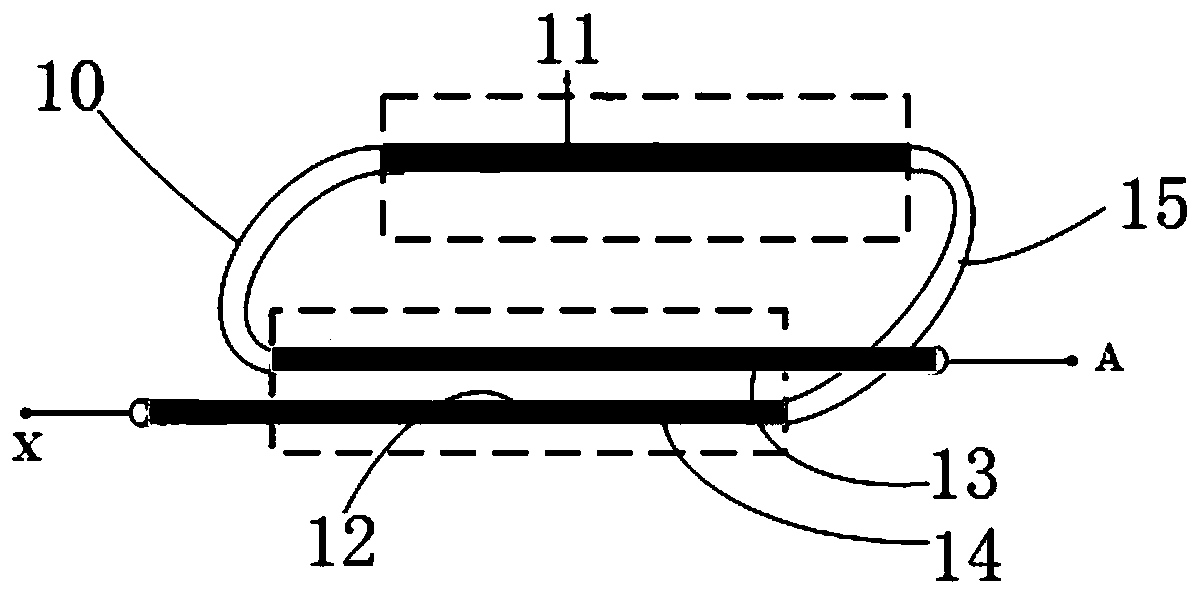
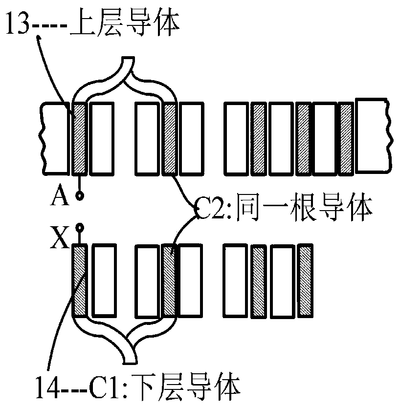
[0035] Such as figure 1 As shown, a winding includes: a plurality of coils; the coil is a 1.5-turn coil, and the coil includes a double-layer body module 12, a first conductor 11 and a connecting conductor module; the double-layer conductor module 12 and the The first conductor 11 is connected through the connecting conductor module; the double-layer conductor module 12 includes: a second conductor 13 and a third conductor 14; the connecting conductor module includes: a first connecting conductor 10 and a second connecting conductor 15; The second conductor 13 and the third conductor 14 are arranged side by side up and down, the input end of the second conductor 13 is the coil input end A, the output end of the third conductor 14 is the coil output end X, and the first The output end of the second conductor 13 is connected with the input end of the first conductor 11 through the first connecting conductor 10, and the output end of the first conductor 11 is connected with the i...

Embodiment 2

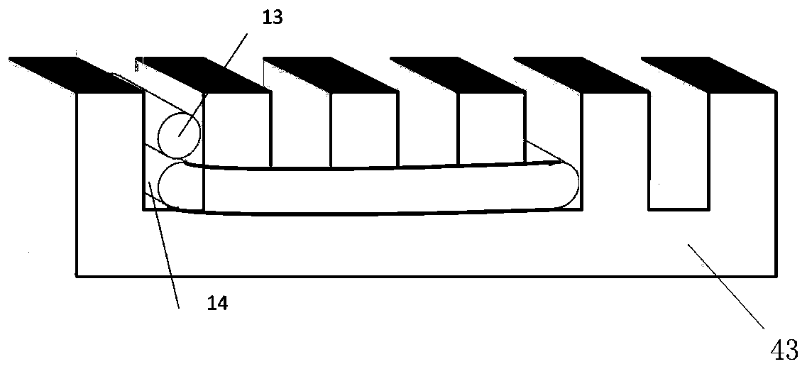
[0040] Such as Figure 2-Figure 3As shown, a stator includes: a stator core 43 and the winding described in Embodiment 1; m stator slots are uniformly arranged on the stator core 43; a double-layer conductor module of the nth coil of the winding (the first A plurality of stator slots are separated between the second conductor 13 and the third conductor 14) and the first conductor of the nth coil of the winding, and the double-layer conductor module of the nth coil of the winding is along the kth stator slot The slot edge of the stator core 43 is set in the kth stator slot of the stator core 43, and the first conductor of the nth coil of the winding is set in the stator core 43 along the slot edge of the k+bth stator slot. In the k+b stator slot; the double-layer conductor module of the n+1 coil of the winding is arranged in the k+b stator slot of the stator core 43 along the slot edge of the k+b stator slot , the first conductor of the n+1th coil of the winding is arranged in...

Embodiment 3

[0042] A motor whose magnetic flux is axially forming a main magnetic circuit, comprising: a rotor core 42, a magnetic steel 41 and the stator described in Embodiment 2, such as Figure 4-Figure 5 As shown, the magnetic steel 41 is arranged in the rotor slot of the rotor core 42 . The distance between the double-layer conductor module and the first conductor of the same coil of the stator is similar to the distance between the magnetic steel 41 in the adjacent rotor slot, which is equal to the pole pitch, shorter than the pole pitch, and longer than the pole pitch Three categories.

[0043] The arrangement equal to the pole distance is as Figure 6 As shown, the distances between the double-layer conductor modules and the first conductor 11 of all coils are equal. One rotor slot corresponds to one magnet steel 41 , the polarity of the magnet steel 41 is S pole or N pole, and the polarity of the magnet steel 41 in adjacent rotor slots is different. Figure 7 It is the view A...


PUM


Abstract

The invention relates to a winding, a stator and a motor. The winding comprises: a plurality of coils; each coil comprises a double-layer conductor module, a first conductor and a connecting conductormodule; the double-layer conductor module is connected with the first conductor through the connecting conductor module; the double-layer conductor module comprises a second conductor and a third conductor; and the connection conductor module comprises a first connection conductor and a second connection conductor. The second conductor and the third conductor are vertically arranged side by side,the output end of the second conductor is connected with the input end of the first conductor through the first connecting conductor, and the output end of the first conductor is connected with the input end of the third conductor through the second connecting conductor. According to the invention, the second conductor and the third conductor are arranged side by side up and down, so that the twoconductors have a capacitance effect under high-frequency pulse potential excitation, the loss is reduced when current flows through the conductors, the electrical load density of the motor can be improved, and the high density of the motor is realized.

Description

technical field [0001] The invention relates to the field of motors, in particular to a winding, a stator and a motor. Background technique [0002] In the industrial field, 60% of the electric energy is used by the motor. In some occasions that require the installation space of the motor, such as the electric drive of the vehicle, the high efficiency and high density index of the motor system has become an important direction of technological development. The high efficiency of the motor is high. Densification is the development goal of the motor industry. It can not only improve the energy efficiency of the system, but also greatly reduce the cost of materials and realize miniaturization. It has obvious practical value in many occasions (such as electric vehicles, aerospace, military industry, etc.). The coil in an ordinary AC motor has an integer number of turns, and the number of turns is generally more than 2 turns. The coil of a conventional AC motor exceeds two turns ...

Claims


Application Information

Patent Timeline
Patent Type & Authority Applications(China)
IPC IPC(8): H02K3/04H02K3/12H02K3/28H02K1/16H02K1/27
CPCH02K1/165H02K1/2766H02K3/04H02K3/12H02K3/28H02K2213/03Y02T10/64
Inventor 徐国卿徐霄宇谭协初
Owner SHANGHAI UNIV
Why Eureka
Try Eureka