Electrical switchgear with rotating mobile contact(s)

A technology of electrical switches and moving contacts, applied in electrical switches, electrical components, protection switches, etc., can solve the problems of pollution, discontinuity, and difficulty in increasing the leakage distance.

Active Publication Date: 2009-07-08
SCHNEIDER ELECTRIC IND SAS
View PDF7 Cites 2 Cited by
  • Summary
  • Abstract
  • Description
  • Claims
  • Application Information

AI Technical Summary

Problems solved by technology

[0004] Also, in some embodiments, the rotational coupling is performed on the edge of the movable contact, which can cause contamination and lead to the disadvantage of discontinuity
[0005] Also, in these embodiments, it is difficult to increase the creepage distance since the separated bulkheads would exceed the dimensions
[0006] Furthermore, the complex shape of the contacts means that the amount of copper has to be increased accordingly

Method used


Image

  • Electrical switchgear with rotating mobile contact(s)
  • Electrical switchgear with rotating mobile contact(s)
  • Electrical switchgear with rotating mobile contact(s)

Examples


Embodiment Construction

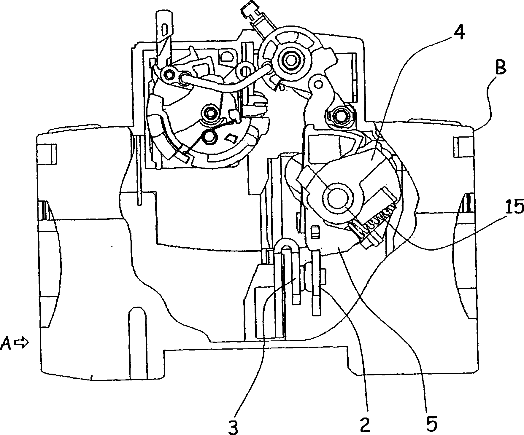
[0030] For purposes of illustration, these figures show the application of the invention to an electrical switching unit such as a differential switch of the type described in French patent FR 2870987 .

[0031] This electrical unit is likewise well known and, since it is not the subject of the present invention, it will not be described in detail here. Only elements necessary for understanding the present invention will be described.

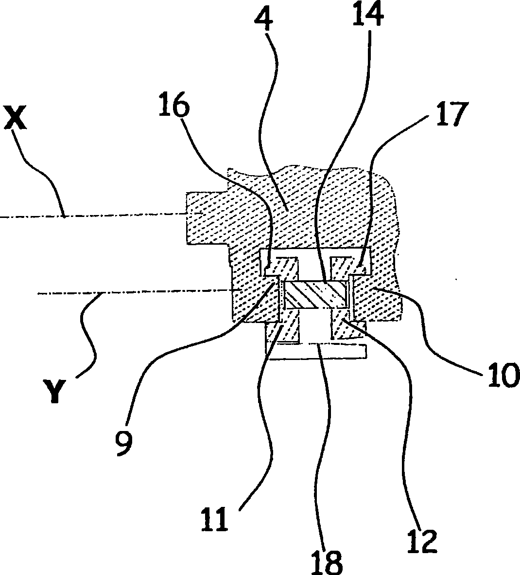
[0032] The electrical unit A comprises in a housing B, in a known manner, a movable contact holder 4 , 5 mounted to rotate in the housing B; a movable contact 2 mounted facing at least one stationary contact 3 . The movable contact holder is mounted to rotate between an open position of the contacts, in which the movable contact 2 is separated from the static contact 3, and a closed position, in which the movable contact 2 is pressed against the On the static contact 3.

[0033] This movable contact bracket comprises a first bracket 4 mounted...


PUM


Abstract

The invention relates to an electrical switch unit A contained in an insulating housing B and comprising a contact bracket used for supporting at least a contact (2) called movable contact and for setting the movable contacts and each movable contact (2) to face to at least a contact (2) called still contact. The unit is characterized in that the contact (2) can be arranged in a bracket (5) called a second bracket (or movable contact are arranged brackets called second brackets respectively); the second bracket (5) is hinged with respect to the first bracket (4); and the unit comprises a device used for providing contact pressure between the movable contacts and the still contacts.

Description

technical field [0001] The present invention relates to an electrical switching unit housed in an insulating housing and comprising a contact holder supporting at least one movable contact, the or each movable contact being arranged to face a At least one static contact of the unit, the bracket is mounted to rotate between an open position, where the movable contact is separated from the static contact, and a closed position, where the movable contact is separated from the fixed contact, and a closed position, where the movable contact is separated from the Static contact. Background technique [0002] Known patents US 5794763, FR 2717613 and EP 0773566 disclose devices comprising the features described above. In these embodiments, the movable contact is mounted in a contact support shaft and a spring is placed between the contact and the shaft so that the spring retains the contact in its Contact pressure is provided between the contact and the static contact. [0003] A...

Claims


Application Information

Patent Timeline
IPC IPC(8): H01H71/02H01H73/04H01H1/22H01H1/50
CPCH01H1/226H01H1/225
Inventor 劳伦特·普里维厄克斯伊维斯·布龙克劳德·伯诺特罗兰·马斯纳达
Owner SCHNEIDER ELECTRIC IND SAS
Why Eureka
Try Eureka