Synchronmaschine eines innenpermanentmagnettyps

一种同步机、扇形段的技术,应用在同步机零部件、带有静止电枢和旋转磁体的同步电动机、机电装置等方向,能够解决不够、增加输出转矩等问题

Active Publication Date: 2009-07-08
DENSO CORP
View PDF1 Cites 31 Cited by
  • Summary
  • Abstract
  • Description
  • Claims
  • Application Information

AI Technical Summary

Problems solved by technology

[0006] However, the conventional reluctance parallel use magnetic synchronous machine is insufficient for increasing the output torque, the synchronous machine is forced to use a large number of very expensive rare earth magnets

Method used


Image

  • Synchronmaschine eines innenpermanentmagnettyps
  • Synchronmaschine eines innenpermanentmagnettyps
  • Synchronmaschine eines innenpermanentmagnettyps

Examples


no. 1 example

[0027] refer to figure 1 -2. An internal permanent magnet (IPM) type synchronous machine according to a first embodiment of the present invention will be described.

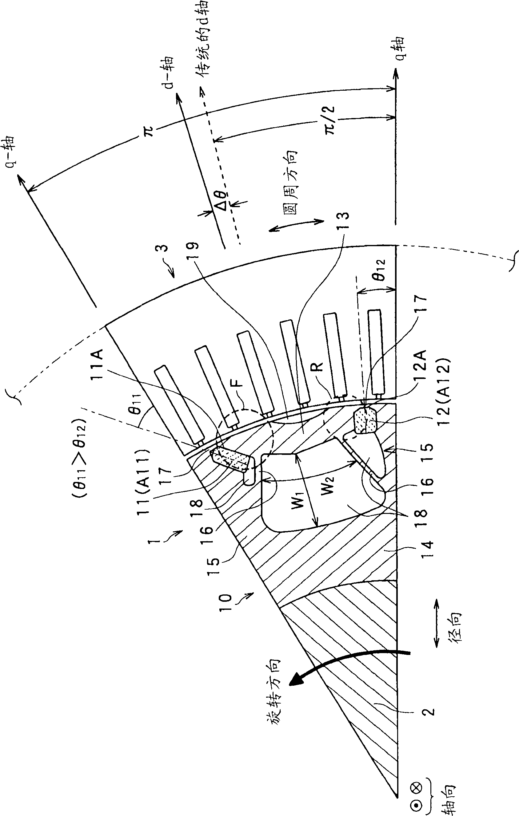
[0028] figure 1 is a partial sectional view of the rotor of a synchronous machine, cut axially to show the internal partial structure of the rotor.

[0029] exist figure 1 In the shown structure, there are a rotor 1 , a rotating shaft 2 , and a stator 3 . The stator 3 is provided with a stator core having slots and teeth formed on its inner surface, and a stator coil wound in the slots. Since the structure of such a stator core is known, its detailed description will be omitted here.

[0030] The rotor 1 is provided with a rotor core 10 made of soft magnetic material, front side permanent magnets 11 , rear side permanent magnets 12 and segments made of soft magnetic material. In the current embodiment, "front, front, or front side" and "rear or rear side" are in the direction of rotation ( figure 1 The coun...

no. 2 example

[0071] refer to Figure 11 , a second embodiment of the synchronous machine according to the invention will now be described. In the present embodiment and subsequent embodiments, the same or similar elements as those in the first embodiment are given the same reference numerals in order to reduce description.

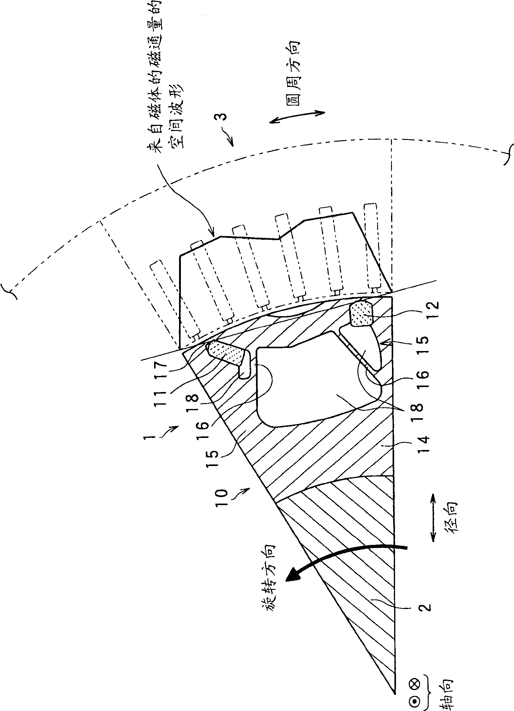
[0072] Figure 11 A partial sectional view of the rotor 2 according to the present embodiment is shown. The rotor 2 is designed as an outer rotor. In this outer rotor structure, the inter-segment / inter-yoke non-magnetic portion 180 formed in the rotor 2 is filled with resin as a non-magnetic material. This filling technique allows the portion 180 to support the segments 13 and the permanent magnets 11 and 12 by itself, greatly improving the resistance to centrifugal forces.

[0073] That is, in the outer rotor structure, resistance to centrifugal force does not have to be considered so much that rotation performance at higher speeds can be greatly improved.

no. 3 example

[0075] refer to Figure 12-15 , a third embodiment of the synchronous machine according to the invention will now be described.

[0076] In the current embodiment, the rear connecting portion is removed from the structure, so that the rear end of the segment 13 in the rotational direction is separated from the rear end side of the convex magnetic pole 15, as Figure 12 and 14 shown.

[0077] This separation structure prevents the sector 13 from generating tensile stress therein due to forces induced in rotation pulling the distal end and rear end of the sector 13 in opposite directions, respectively. It is thus possible to reduce the width of the front connecting portion 17 in the radial direction. In addition, the leaking magnetic flux can be reduced at the rear end of the segment 13 because there is no connection there.

[0078] In addition, if Figure 13 and 14 As shown, the front and rear side permanent magnets 11 and 12 are produced such that the widths of the magne...


PUM


Abstract

A synchronous machine comprises a stator and a rotor that faces the stator and rotates on a shaft thereof in a circumferential direction The rotor has magnetic salient poles that generate reluctance torque and magnet-originating magnetic poles that generate magnet torque by using permanent magnets embedded in the rotor, The machine comprises means for shifting a magnetically substantial central position of magnetic flux emanating from the permanent magnets in the circumferential direction, by an electrical angle pi / 2 plus a predetermined angle Deltatheta, from a reference position taken as a central position between paired magnetic salient poles composing each magnetic pole of the machine among the magnetic salient poles. Hence a maximum amplitude of a sum between a harmonic component of the magnet torque and the reluctance torque is changed from that obtained at the reference position without the shift.

Description

technical field [0001] The present invention relates to IPM (Inner Permanent Magnet) type synchronous machines, and in particular, to IPM type synchronous machines that generate magnetic torque and reluctance torque. Background technique [0002] There is known a synchronous machine that generates magnetic torque and reluctance torque (hereinafter, such a synchronous machine will be referred to as a reluctance parallel use magnetic synchronous machine). One of the most familiar magnetic synchronous machines for reluctance parallel use is the IPM (Internal Permanent Magnet) type synchronous motor. [0003] When there is a difference between the q-axis inductance Lq and the d-axis inductance Ld, the reluctance torque Tr is obtained, because the reluctance of the permanent magnet is large, the q-axis inductance Lq is generally made larger than the d-axis inductance Ld in terms of strength . However, this is not the only possible structure. The d-axis inductance Ld can be mad...

Claims


Application Information

Patent Timeline
Patent Type & Authority Applications(China)
IPC IPC(8): H02K21/14H02K21/02H02K1/27
CPCH02K1/276H02K1/246
Inventor 七条彰哉草濑新水间裕也伊藤智
Owner DENSO CORP
Why Eureka
Try Eureka