Voltage stabilizing circuit having time keeping function

A technology for holding time and voltage stabilizing circuits, which is applied in the direction of conversion equipment without intermediate conversion to AC, which can solve the problems of peak current protection circuit misoperation, large current, and reliable and effective protection of power modules, so as to avoid startup difficult effect

Active Publication Date: 2009-07-08
EMERSON NETWORK POWER CO LTD
View PDF0 Cites 5 Cited by
  • Summary
  • Abstract
  • Description
  • Claims
  • Application Information

AI Technical Summary

Problems solved by technology

On the one hand, the peak protection is required to be sensitive, but it will cause the charging current of the filter capacitor C1 to be too large during startup and trigger the peak current protection circuit to malfunction, causing the power module to fail to start smoothly, which generally manifests as "hiccups". For this situation, the peak protection action threshold is It should be increased appropriately; on the other hand, the peak current generated by the normal operation of the power module after startup is relatively low, and the action threshold of the peak current protection circuit cannot be designed too high. Than limit
In short, not only the capacity of the filter capacitor C1 is required to be large enough to obtain a longer output voltage holding time, but also to ensure that the power module can be started smoothly, the action threshold of the peak current protection circuit must be designed to a higher value, and at this time This situation occurs: when a short circuit or overcurrent occurs at the output load end, the power module cannot achieve reliable and effective protection, and the current through the rectifier diode D1 will still be very large at this time
That is, by increasing the capacity of the filter capacitor, the output voltage of the three-terminal integrated voltage regulator has a longer holding time function. If a special startup circuit design is not adopted on the primary side control circuit, it will be difficult to start the power module. question

Method used


Image

  • Voltage stabilizing circuit having time keeping function
  • Voltage stabilizing circuit having time keeping function
  • Voltage stabilizing circuit having time keeping function

Examples


specific Embodiment approach 1

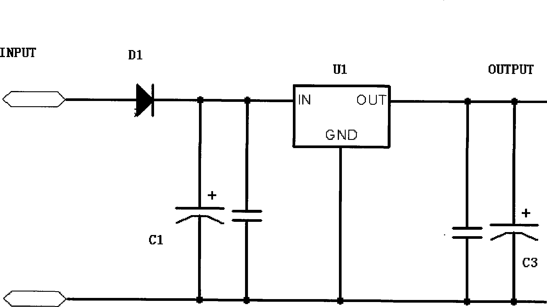
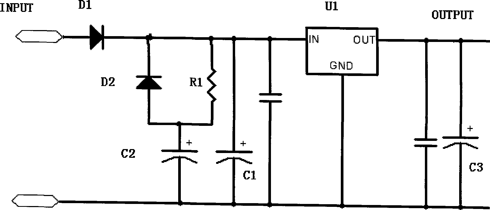
[0022] Such as figure 2 A three-terminal voltage stabilizing circuit with a hold-up time function is shown, including an L7812 linear three-terminal fixed integrated voltage regulator U1 and an input filter capacitor C1 connected in parallel between its input terminal IN and the common ground, and connected in parallel at The output filter capacitor C3 between its output terminal OUT and the common ground, and the rectifier diode D1 connected in series between the input terminal INPUT of the voltage stabilizing circuit and the L7812 linear three-terminal fixed integrated voltage regulator, flow through the rectifier diode D1 The current charges the input filter capacitor C1.

[0023] Between the input terminal IN of the L7812 linear three-terminal fixed integrated voltage regulator U1 and the common ground GND, there is a holding time circuit connected in parallel. The holding time circuit is connected in parallel with the charging resistor R1 and the discharging diode D2 and...

specific Embodiment approach 2

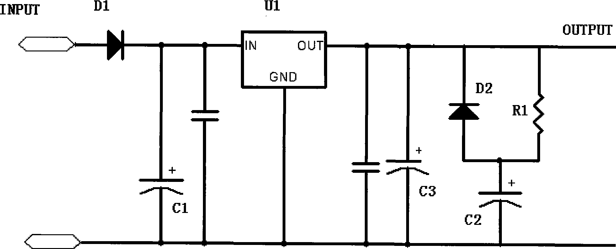
[0026] Such as image 3 Another three-terminal voltage stabilizing circuit with a hold-up time function is shown, which also includes an L7812 linear three-terminal fixed integrated voltage regulator U1 and an input filter capacitor C1 connected in parallel between its input terminal IN and the common ground, The output filter capacitor C3 connected in parallel between its output terminal OUT and the common ground, and the rectifier diode D1 connected in series between the input terminal INPUT of the voltage stabilizing circuit and the L7812 type linear three-terminal fixed integrated voltage regulator, flow through the rectifier The current of diode D1 charges the input filter capacitor C1.

[0027] The difference with the specific embodiment 1 is that the holding time circuit composed of the charging resistor R1 and the discharging diode D2 connected in parallel and then connected in series with the charging and discharging capacitor C2 of any capacity used for the holding t...


PUM


Abstract

A voltage regulator circuit with the function of holding time comprises a three-terminal integrated voltage regulator, an input filter capacitor and a commutation diode. A holding time circuit connected in parallel is provided between input or output terminal of the three-terminal integrated voltage regulator and the common. The holding time circuit is a two-terminal network which is formed by connecting in series with a charge-discharge capacitor for holding time after parallel connection of a charging resistor and a discharge diode. One terminal of the two-terminal network is the cathode of the discharge diode which is connected with the input or output terminal of the three-terminal integrated voltage regulator. The anode of the discharge diode is connected with the anode of the charge-discharge capacitor for holding time. The other terminal is the cathode of the charge-discharge capacitor for holding time is connected with the common. The conventional filter capacitor of the voltage regulator circuit is separated from the charge-discharge capacitor for holding time by the voltage regulator circuit. The charge-discharge capacitor for holding time is the capacitance with optional capacity to ensure the output voltage of the voltage regulator circuit satisfies the holding time required. Then the problem that power module is difficult to be started due to selection of the holding time capacitance with larger capacity can be effectively avoided.

Description

technical field [0001] The invention relates to a voltage stabilizing circuit, in particular to a voltage stabilizing circuit with the function of maintaining time. Background technique [0002] Such as figure 1 The post-stage voltage stabilization circuit of the three-terminal fixed integrated voltage regulator shown is widely used in power supplies. In order to keep the output voltage for a certain period of time, the capacity of the filter capacitor C1 is required to be large enough, and the large-capacity capacitor is used when the power supply starts. When it is equivalent to a short circuit, the larger the capacity of the filter capacitor C1, the higher the current peak value of the rectifier diode D1 charging it and the longer the time. After the charging current is converted to the primary side through the transformer, a higher peak current will be generated, which makes the peak current protection design a difficult problem. On the one hand, the peak protection is...

Claims


Application Information

Patent Timeline
Patent Type & Authority Applications(China)
IPC IPC(8): H02M3/06
Inventor 朱春辉黄晶晶
Owner EMERSON NETWORK POWER CO LTD
Why Eureka
Try Eureka