Voltage falling generator for wind power electricity generation

A technology of voltage drop and generator, which is applied in the direction of wind power generation, conversion equipment that can be converted to DC without intermediate conversion, etc., can solve the problems of high price, poor reliability, and complicated control, and achieve simple operation, good real-time performance, The effect of high reliability

Inactive Publication Date: 2009-07-08
ZHEJIANG UNIV
View PDF2 Cites 22 Cited by
  • Summary
  • Abstract
  • Description
  • Claims
  • Application Information

AI Technical Summary

Problems solved by technology

Chinese patent: CN101149412 discloses a voltage drop simulation generator, which controls the stepper motor to drag the auto-coupling voltage regulator to change the output voltage of the voltage regulator through the input voltage drop command of the host computer. Due to the voltage regulation by mechanical action, it cannot Instantaneous changes in voltage
Chinese patent: CN101119074 discloses a single-phase voltage drop generator in the form of a thyristor transformer. Due to the use of thyristors, voltage switching can only occur at the zero-crossing point of the output current, and the phase of the voltage drop cannot be controlled.
[0009] From the above analysis, it can be seen that among the voltage drop generator solutions disclosed in the literature, only the power electronic converter can realize the controllable duration, drop depth, start and stop phase and drop type of the voltage drop, but this solution is expensive and complicated to control , poor reliability, not conducive to large-scale promotion

Method used


Image

  • Voltage falling generator for wind power electricity generation
  • Voltage falling generator for wind power electricity generation
  • Voltage falling generator for wind power electricity generation

Examples


Embodiment Construction

[0023] The present invention will be further described below in conjunction with the accompanying drawings and embodiments.

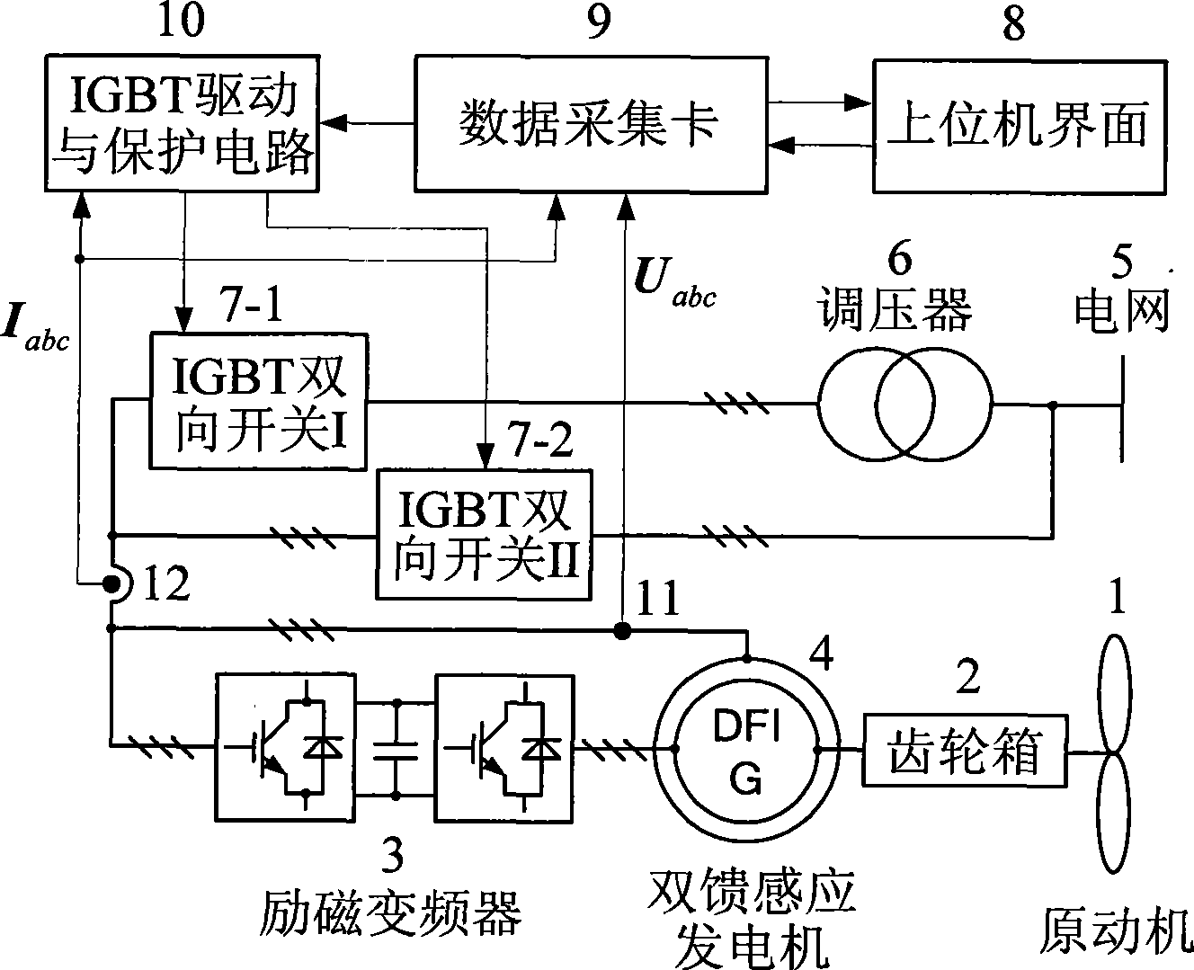
[0024] refer to figure 1 , the voltage drop generator for wind power generation of the present invention includes: host computer 8, data acquisition card 9, IGBT drive and protection circuit 10, IGBT bidirectional switch I7-1, IGBT bidirectional switch II7-2, voltage regulator 6, voltage Hall sensor 11, current Hall sensor 12, and wind turbine; wherein the wind turbine is composed of prime mover 1, gearbox 2, excitation frequency converter 3, and double-fed induction generator 4. The data acquisition card 9 is connected to the upper computer 8 and the IGBT drive and protection circuit 10; the input terminal of the IGBT bidirectional switch I7-1 is connected to the secondary side of the voltage regulator 6, and the input terminal of the IGBT bidirectional switch II7-2 is connected to the secondary side of the voltage regulator 6 The primary side is conn...


PUM


Abstract

The invention discloses a voltage-dip generator used for wind power generation. The voltage-dip generator comprises a host computer, a data collecting card, an IGBT driving and protecting circuit, two IGBT bilateral switches, a booster, a voltage Hall sensor, a current Hall sensor and a wind turbine generator. Three-phase voltage signals and three-phase current signals output by the voltage-dip generator are obtained by the voltage Hall sensor and the current Hall sensor; the three-phase voltage signals and the three-phase current signals output by the voltage-dip generator are acquired by the data collecting card and transmitted to the host computer; the host computer outputs voltage-dip signals and restores instruction signals to the IGBT driving and protecting circuit through the data collecting card, and leads the two IGBT bilateral switches to conduct alternately; and the voltage output by the voltage-dip generator is switched over between a primary side and a secondary side of the booster, thereby simulating various symmetrical and unsymmetrical network voltage dip faults. The voltage-dip generator has the characteristics of simple operation, high reliability, good real-time performance, etc., and is suitable for performance test and research of the wind turbine generator when in network voltage faults.

Description

technical field [0001] The invention relates to a voltage drop generator meeting the requirements of the IEC61000-4-11 and GB / T17626.11 standards, which is especially suitable for the low voltage ride-through operation test of the wind power generating set, and can also be used for other electrical and electronic products when the grid voltage fails. performance testing and research under the circumstances. Background technique [0002] Modern large-scale wind power generation systems mainly include doubly-fed induction generators and permanent magnet synchronous generators, among which doubly-fed induction generators are the current mainstream models. At present, my country's wind power technology mostly stays in the operation control under ideal grid conditions. Since various symmetrical and asymmetrical faults often occur in the actual grid, it is necessary to carry out research on operation control under grid faults. In recent years, a variety of wind turbine grid-conne...

Claims


Application Information

Patent Timeline
IPC IPC(8): H02M5/10H02M5/12
CPCY02E10/76
Inventor 周鹏贺益康章玮
Owner ZHEJIANG UNIV
Why Eureka
Try Eureka