
Motor speed detection method

A speed detection and speed technology, applied in linear/angular speed measurement, speed/acceleration/shock measurement, motor control, etc., can solve problems such as unstable motor speed, large phase lag, and filter order limit, etc., to reduce costs Effect

Inactive Publication Date: 2009-07-08
东元总合科技(杭州)有限公司
View PDF0 Cites 7 Cited by
  • Summary
  • Abstract
  • Description
  • Claims
  • Application Information

AI Technical Summary

Problems solved by technology

However, adding a filter will cause a phase lag. If there is no special requirement and it is not at low speed, it can still meet the requirements. At very low speed, the obtained motor speed is not stable.
And from the perspective of implementation, there are also certain restrictions on the order of the filter. If the order is too high, the implementation will become complicated and the phase lag will be larger. However, if the order is not enough, it cannot effectively smooth the speed fluctuation in some cases.

Method used


Image

  • Motor speed detection method
  • Motor speed detection method
  • Motor speed detection method

Examples


Embodiment 1

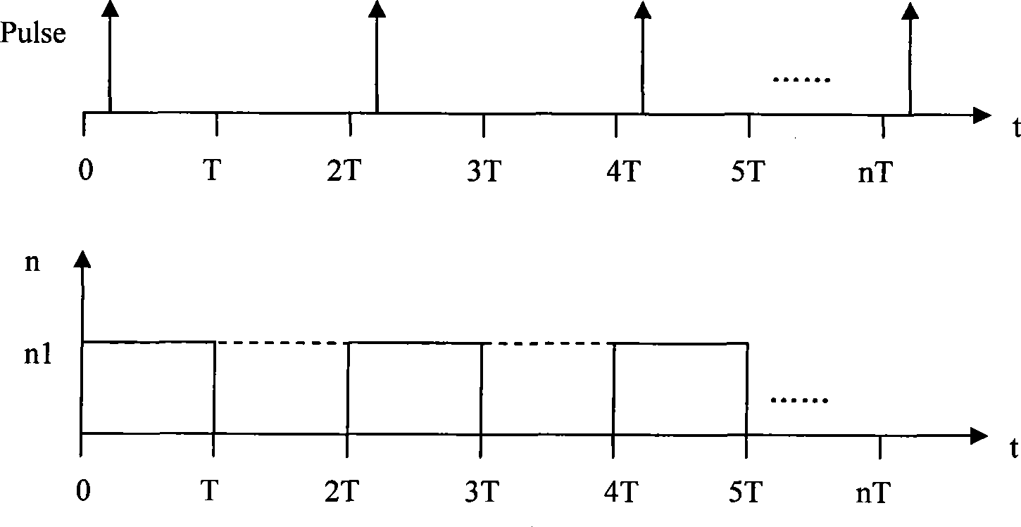
[0026] In the existing speed detection method, for a speed control cycle in which the pulse is zero, the motor speed in the cycle is zero; for a speed control cycle in which the pulse is not zero, the motor speed in the cycle is zero. n = 60 · M P · T p rpm , Among them, M is the number of pulses detected in the speed control cycle, P is the number of encoder lines, and T p is the pulse sampling interval.

[0027] When the motor is at high speed, each speed control cycle (pulse sampling interval T p It is equal to the speed control cycle) and pulses can be detected, but when the motor is at low speed, pulses may or may not be detected in the speed control cycle.

[0028] Such as figure 2 As shown, the motor speed control period and the original pulse sampling interval ...

Embodiment 2

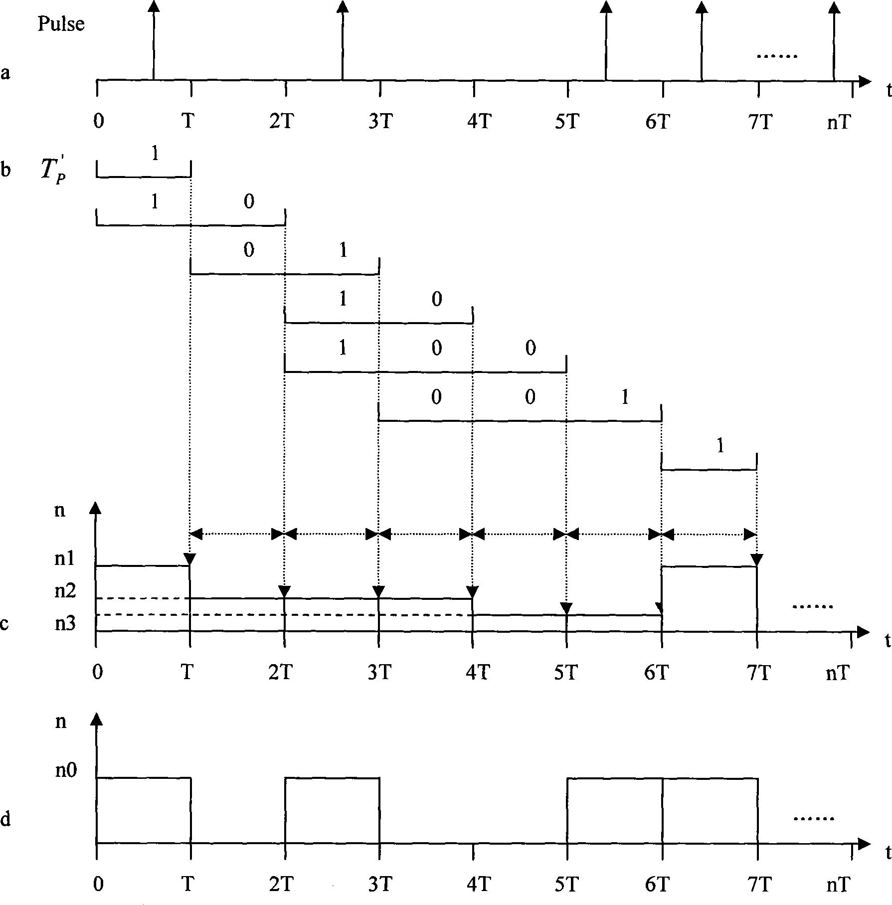
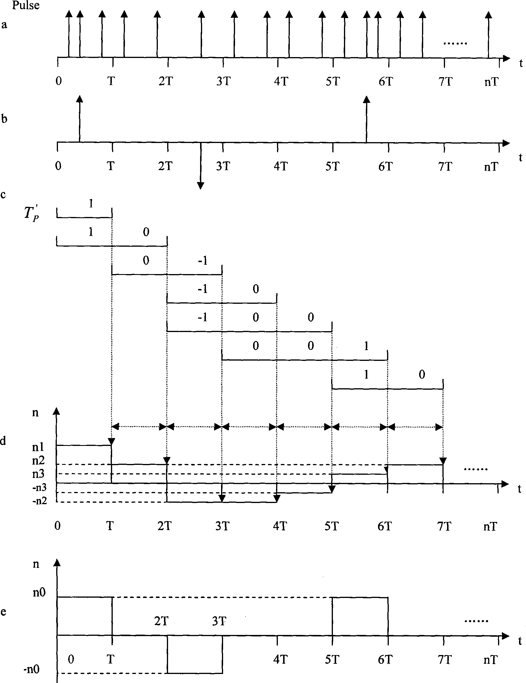
[0039] When the motor is in a high speed state, pulses can be detected every speed control cycle, such as image 3 As shown in a, each speed control cycle has at least one pulse. When processing, the pulse number of a certain speed control cycle can be used as the reference pulse number. The more accurate processing method is to use the maximum pulse number and the minimum pulse number of the speed control cycle to average and then round up as the reference pulse number. For example, this In the embodiment, the maximum pulse number of the speed control cycle is 3, and the minimum pulse number is 1, so the reference pulse number should be selected as 2. If the maximum pulse number and the minimum pulse number of the speed control cycle are not an integer after being averaged, then it can be obtained after taking Determine the number of reference pulses after adjustment.

[0040] After determining the number of reference pulses, according to the number of reference pulses and t...


PUM


Abstract

The invention provides a motor speed detection method for detecting the motor speed at an extremely low speed and an high speed. In the motor speed detection method, self-defined impulse sampling interval is adopted to replace impulse sampling interval to perform the calculation of the motor speed without changing the impulse sampling interval and speed control period. The motor speed detection method enables the detection of the accurate motor mean velocity, realizes the steady speed control when in extremely low speed range and high speed of a motor by utilizing the rapid speed adjustment characteristic, and effectively lowers the cost of a speed control system at the same time by adopting a pulse encoder with low resolution and low cost.

Description

technical field [0001] The invention relates to a motor detection technology, in particular to a motor speed detection method. Only a low-resolution pulse coder is used to detect the motor speed, so that a more accurate motor speed can be obtained for motor control. Background technique [0002] In a motor speed control system, if only a pulse encoder with relatively low resolution is used, when the motor rotates at a very low speed, the adjacent time interval of the pulses obtained from the pulse encoder (each pulse rising edge Period or falling edge period) is usually greater than the motor speed control period and pulse sampling interval, so there is no pulse signal in one speed control period, so that accurate motor speed feedback information cannot be obtained. [0003] Velocity measurement resolution characterizes the sensitivity of the measurement device to changes in rotational speed. Under low-resolution pulse encoder velocity measurement, the velocity measurement r...

Claims


Application Information

Patent Timeline
Patent Type & Authority Applications(China)
IPC IPC(8): H02P29/00G01P3/481
Inventor 邹积浩董海军
Owner 东元总合科技(杭州)有限公司
Learn More