Starting circuit for bias circuit

A technology of starting circuit and bias circuit, which is applied in the direction of electrical components, electronic switches, pulse technology, etc., can solve the problems that the starting circuit cannot generate current, increase the starting time, and have no requirement for standby current.

Inactive Publication Date: 2009-07-08
UNIBAND ELECTRONICS CORP
View PDF0 Cites 1 Cited by
  • Summary
  • Abstract
  • Description
  • Claims
  • Application Information

AI Technical Summary

Problems solved by technology

When the supply voltage drops, the start-up circuit will not be able to generate the same current as when the supply voltage is high, which will increase the start-up time
[0005] Nowadays, many different starting circuits have been proposed, but some starting circuits cannot meet the requirements of a wide range of voltage supply or no standby current requirements, and some starting circuits cannot meet the requirements of short startup time or simple circuit design.

Method used


Image

  • Starting circuit for bias circuit
  • Starting circuit for bias circuit
  • Starting circuit for bias circuit

Examples


Embodiment Construction

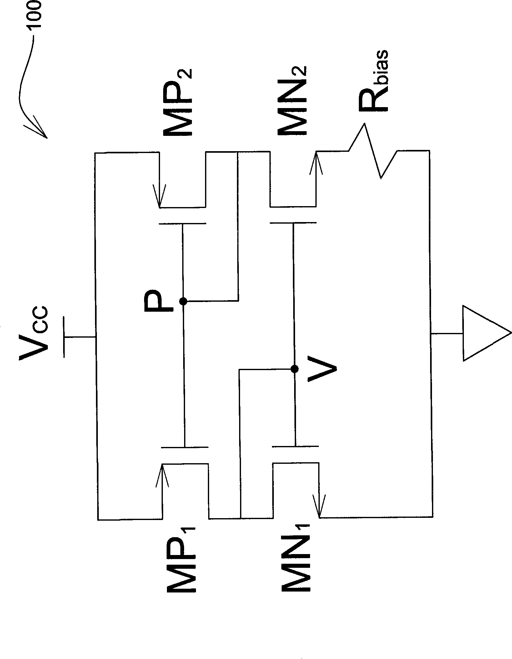
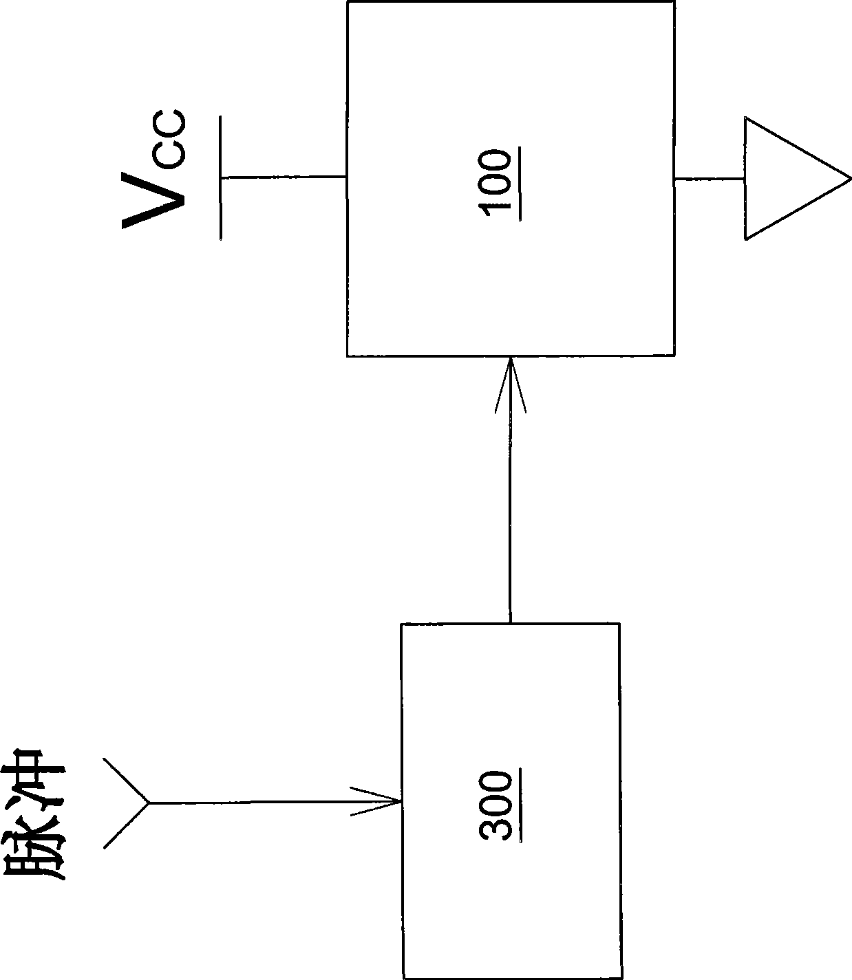
[0026] figure 2 It is a schematic diagram of starting circuit to bias circuit. As shown, the startup circuit includes a switch 300 coupled to the bias circuit 100 . The switch 300 receives a pulse, for example, a pulse from a pulse supplier will turn on the switch 300 , and the switch 300 will send an activation signal to activate the bias circuit 100 . Immediately after the pulse, the switch 300 will close to stop the operation of the starting circuit.

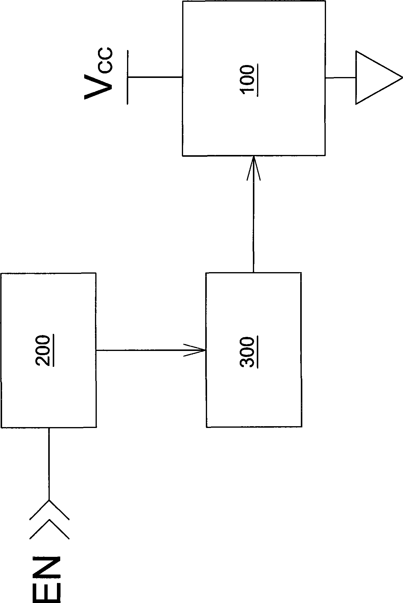
[0027] image 3 As an embodiment of the present invention, a schematic diagram illustrating the connection of the start-up circuit and the bias circuit 100 is illustrated. The startup circuit includes a pulse generator 200 and a switch 300 . The pulse generator 200 receives an enabling voltage, image 3 is marked as EN, and at least one pulse voltage is sent later to control the switch 300 . Various pulse generator 200 embodiments are shown in Figure 4a and Figure 4b , a different switch 300 is shown in the Figur...


PUM


Abstract

The invention provides a starting circuit of a bias circuit, which utilizes a switch to provide an actuated signal so as to draw the bias circuit out of a null state, the switch is driven by a pulse from an external pulse provider or a combined pulse generator, the bias circuit enters a stable operating state after the pulse, and the starting circuit stops operating. Therefore, the starting circuit has the advantages of large-scale voltage supply, no standby current, short starting time, simple circuit layout, etc.

Description

technical field [0001] The invention relates to a start-up circuit which does not consume standby current and can be applied to a wide range of voltage supplies. Background technique [0002] The start-up circuit is used to pull up a zero-state (also referred to as zero-current state) bias circuit to a stable operating state to activate an electronic device. An ideal start-up circuit requires no standby current, simple circuit design, application to a wide range of supply voltages, and short start-up time. [0003] figure 1 It is a schematic diagram of a bias circuit, used to describe a conventional bias circuit in conjunction with the following paragraphs. One end of the bias circuit 100 is connected to a voltage source of a voltage VCC, and the other end is grounded. The bias circuit 100 includes a left leg and a right leg to form a current-mirror-based bias circuit. The left bridge arm contains a p-channel metal oxide silicon field effect transistor (PMOS) MP 1 and a...

Claims


Application Information

Patent Timeline
Patent Type & Authority Applications(China)
IPC IPC(8): H03K17/687
Inventor 陈政宏
Owner UNIBAND ELECTRONICS CORP
Why Eureka
Try Eureka