Light control automatic gain control circuit applied on cable television network optical receiver

A technology of cable TV network and automatic gain control, which is applied in the direction of TV system, electrical components, and cable transmission adapting to optical transmission, which can solve problems that are difficult to eliminate, and achieve the effect of simple debugging, not easy to interfere, and stable and reliable control

Inactive Publication Date: 2009-07-08
SHANGHAI UNIV +1
View PDF0 Cites 18 Cited by
  • Summary
  • Abstract
  • Description
  • Claims
  • Application Information

AI Technical Summary

Problems solved by technology

The disadvantage of this method is that it needs to perform analog-to-digital and digital-to-analog conversion. The frequency of the crystal oscillator used in the single-chip microcomputer is generally a few MHz to a dozen MHz, and it is a square wave with a wide harmonic spectrum, ranging from tens of MHz to hundreds of MHz. MHz, it is very prone to radiated interference, so it is a very troublesome source of interference
AGC with wide control range and high control precision requires high control precision of A / D, and if digital control produces interference, it will be very difficult to eliminate

Method used


Image

  • Light control automatic gain control circuit applied on cable television network optical receiver
  • Light control automatic gain control circuit applied on cable television network optical receiver
  • Light control automatic gain control circuit applied on cable television network optical receiver

Examples


Embodiment Construction

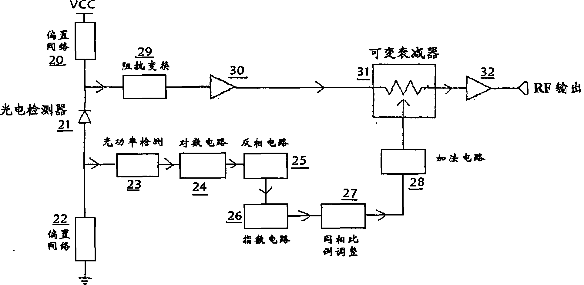
[0027] A preferred embodiment of the present invention is described as follows in conjunction with accompanying drawing:

[0028] see image 3 , the optical control automatic gain control circuit applied to the cable TV network optical receiver, including bias network 20, photodetector 21, bias network 22 and variable attenuator 31; (1) described photodetector 21 respectively By bias network 22 and bias network 20 grounding and connection power supply, and bias network 22 output connections; (2) an optical power detection circuit 23 detects output optical power, and its output connection; (3) a logarithm Circuit 24 performs logarithmic operation to the output of optical power detection circuit 23, and its output is connected; (4) an inverting circuit 25 reverses the output voltage of logarithmic circuit 24, and its output is connected; (5) an index circuit 26, logarithmic operation is done to the output of inverting circuit 25, and its output is connected; (6) a same-phase ra...


PUM


Abstract

The invention relates to an optically-controlled automatic gain control circuit applied to an optical receiver of cable television network, which comprises two offset networks, a photoelectric detector and a variable attenuator. The photoelectric detector is grounded and connected with a power source via the two offset networks. The output terminal of the photoelectric detector is connected with an optical power detecting circuit, a logarithmic circuit, a phase inverting circuit, an exponential circuit, a phase proportion adjusting circuit and an adding circuit in sequence, and then is connected with the variable attenuator, thereby achieving the automatic gain control (AGC). The circuit is implemented by use of the pure analog hardware, and can control the input light power in the range above 10dB, namely, the radio-frequency output level in the range above 20dB.

Description

technical field [0001] The invention relates to a circuit of an optical receiver applied to a cable television network, and more specifically relates to an optical control automatic gain control circuit of an optical receiver. Background technique [0002] Whether it is the traditional fiber-coaxial hybrid network (HFC), or the FTTC (fiber-to-the-curb), FTTB (fiber-to-the-building) and FTTH (fiber-to-the-home) networks that operators are gradually promoting, signal transmission requires large dynamic range. Usually, for network design, it is hoped that the user end can receive a stable power level, therefore, the network design needs to carry out level control, no matter it is manual or automatic. [0003] For the traditional HFC network, the receiving dynamic range of the general optical node is designed to be small when the network is designed, and it is generally designed to receive at -1dBm, and the number of users covered by a single optical node on the optical distrib...

Claims


Application Information

Patent Timeline
Patent Type & Authority Applications(China)
IPC IPC(8): H04B10/12H04N7/22H04B10/294
Inventor 陈海辉杨威胡斌林如俭
Owner SHANGHAI UNIV
Why Eureka
Try Eureka