
Steel wire rope damage detection method based on electromagnetic chromatography imaging technique

An electromagnetic tomography and damage detection technology, applied in the direction of material magnetic variables, etc., can solve the problems of lack of accuracy in the detection of the wire rope to be detected, the inability to get rid of the one-dimensional signal processing method, and the large attenuation of the surface damage of the magnetic flux leakage signal. The effect of low weight, avoidance of wear, and extended service life

Active Publication Date: 2012-10-31
HARBIN INST OF TECH SHENZHEN GRADUATE SCHOOL
View PDF0 Cites 0 Cited by
  • Summary
  • Abstract
  • Description
  • Claims
  • Application Information

AI Technical Summary

Problems solved by technology

[0005] In order to solve the problem that the electromagnetic detection method in the prior art cannot uniformly evaluate the internal damage and surface damage of the steel wire rope, the magnetic flux leakage signal of the internal damage will be attenuated more than the surface damage due to the shielding effect of the surrounding steel wires , which is not conducive to the technical problem of using a unified standard for damage judgment and the use of multiple Hall sensors to detect circumferential magnetic flux leakage, and output each sensor signal through an independent channel. This flaw detection method has a certain circumferential resolution for defects. The identification and positioning are obtained by analyzing the one-dimensional signals of multiple channels and comprehensively analyzing the results. It is impossible to get rid of the one-dimensional signal processing method, which leads to the technical problem of lack of accuracy in the detection of the internal damage of the steel wire rope to be detected. The present invention provides an electromagnetic layer-based Wire rope damage detection device based on analytical imaging technology

Method used


Image

  • Steel wire rope damage detection method based on electromagnetic chromatography imaging technique
  • Steel wire rope damage detection method based on electromagnetic chromatography imaging technique
  • Steel wire rope damage detection method based on electromagnetic chromatography imaging technique

Examples


Embodiment Construction

[0024] The present invention is described in detail below in conjunction with accompanying drawing and embodiment:

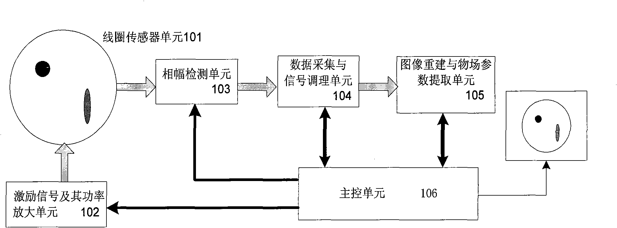
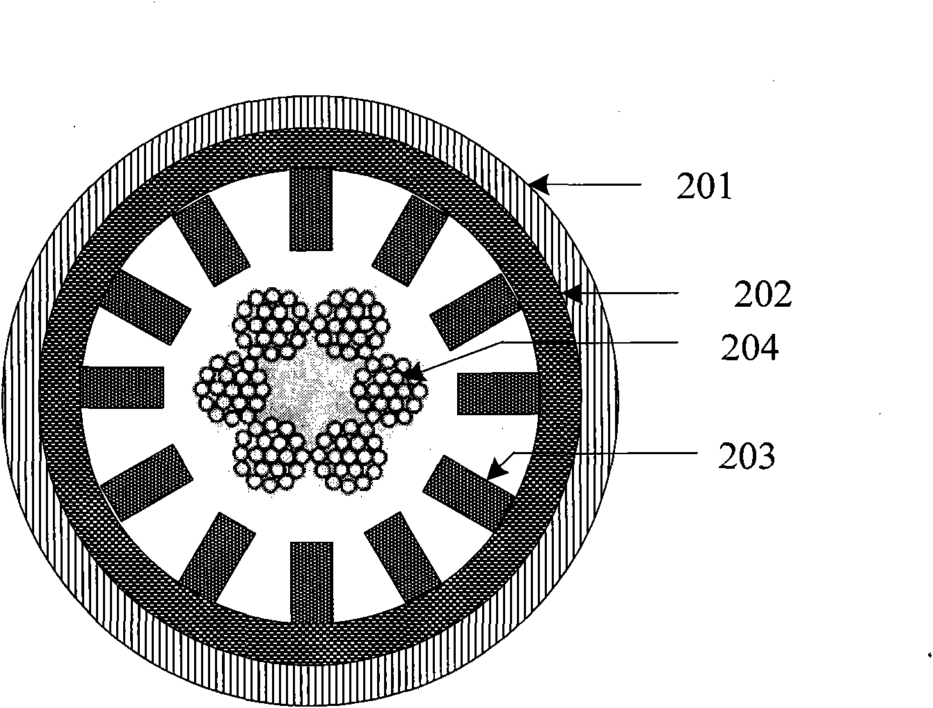
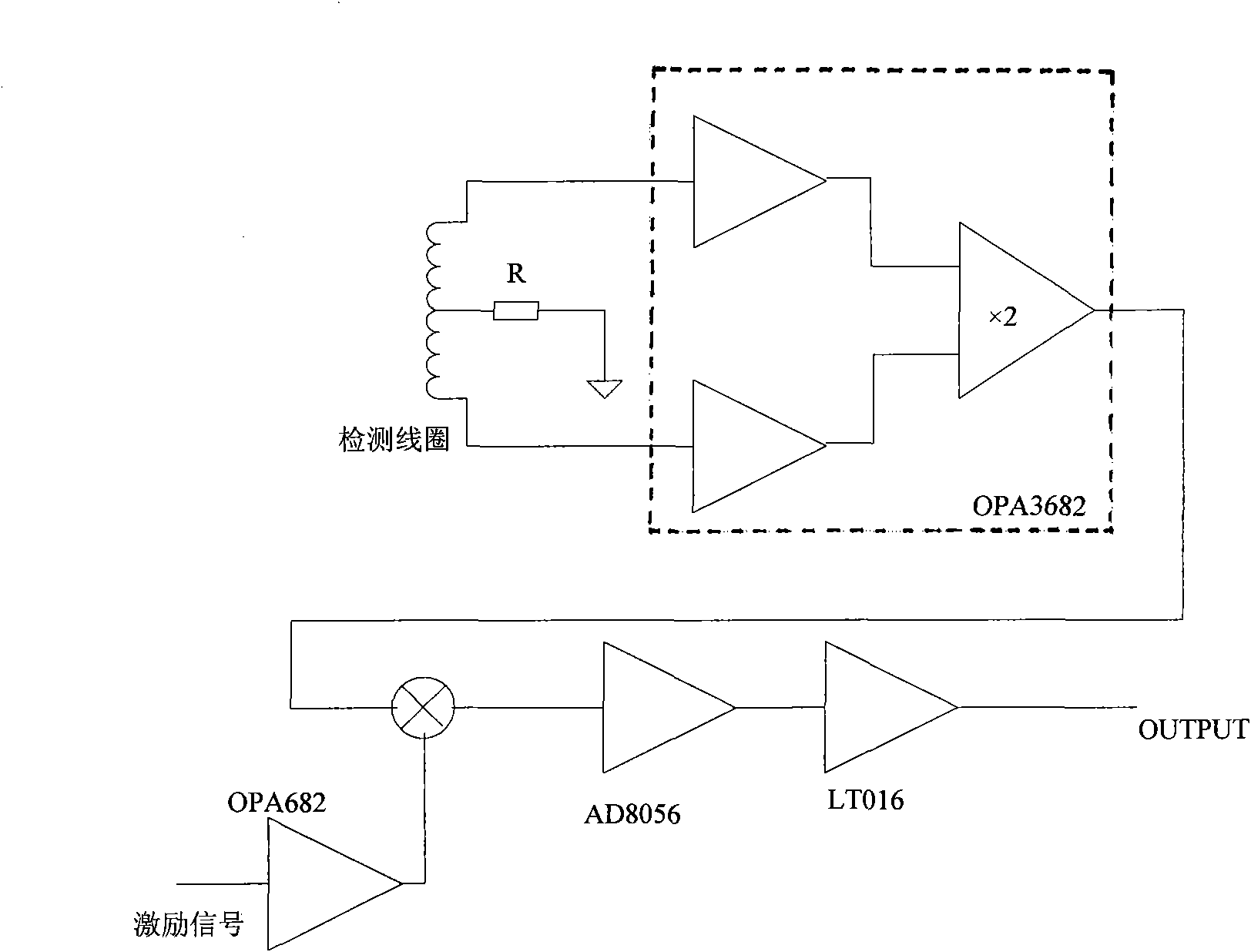
[0025] see figure 1 A schematic diagram of the module structure of the wire rope damage detection device based on the electromagnetic tomography technology in the wire rope damage detection device and method based on the electromagnetic tomography technology of the present invention. Such as figure 1 As shown, the wire rope damage detection device based on electromagnetic tomography technology includes: coil sensor unit 101, excitation signal and its power amplification unit 102, phase amplitude detection unit 103, data acquisition and signal conditioning unit 104, image reconstruction and object A field parameter extraction unit 105 and a main control unit 106 for image and parameter display, wherein the coil sensor unit 101, the excitation signal and its power amplification unit 102, the phase amplitude detection unit 103 and the data acquisition Connected t...


PUM


Abstract

The invention relates to a wire rope damage detection device and method thereof based on electromagnetic tomography technique. The detection device comprises a chart sensor unit, an excitation signal and its power amplifier unit, an amplitude-phase detection unit, a data acquisition and signal conditioning unit, an image reconstruction and object-field parameter extraction unit and main control unit. The detection method comprises: generating the sine excitation signal by a digital synthesizer and amplifying the power by an excitation signal amplifier and generating the excitation field by anexcitation coil; detecting the changed signal of the excitation field by a coil sensor; simultaneously demodulating the detection signal and excitation signal by an amplitude-phase detection circuit to obtain the phase shift between the two signals and the amplitude of the detection signal; normalizing the phase shift and the amplitude signal; performing the inversion imaging of the normalized phase shift signal to obtain the section damage image of the wire rope; quantitatively evaluating the wire rope damage by the image.

Description

【Technical field】 [0001] The invention relates to a steel wire rope damage detection technology, in particular to a wire rope damage detection device and method based on electromagnetic tomography technology. 【Background technique】 [0002] In many industries such as metallurgy, shipping, tourism, ports and construction, steel wire ropes have been widely used. During the use of steel wire ropes, safety accidents caused by wire rope damage directly endanger personal safety and equipment safety. Therefore, real-time monitoring of steel wire ropes The damage condition and its load capacity have important social and economic benefits. [0003] At present, the electromagnetic method is the most widely used and the best effect for wire rope damage detection. This measurement method has basically realized the quantitative detection of cross-section loss by the main magnetic flux method. For local damage, the output of the existing non-destructive detection sensor for steel wire ro...

Claims


Application Information

Patent Timeline
Patent Type & Authority Patents(China)
IPC IPC(8): G01N27/82
Inventor 张东来赵敏
Owner HARBIN INST OF TECH SHENZHEN GRADUATE SCHOOL
Learn More