

Calibration method for amplitude and phase variable array antenna
An array antenna and phase technology, which is applied in the field of aerospace measurement and control, can solve problems such as long time consumption and complex data processing process, and achieve the effect of simple operation process and simple solution.
- Summary
- Abstract
- Description
- Claims
- Application Information
AI Technical Summary
Problems solved by technology
Method used
Image

Examples
Embodiment Construction
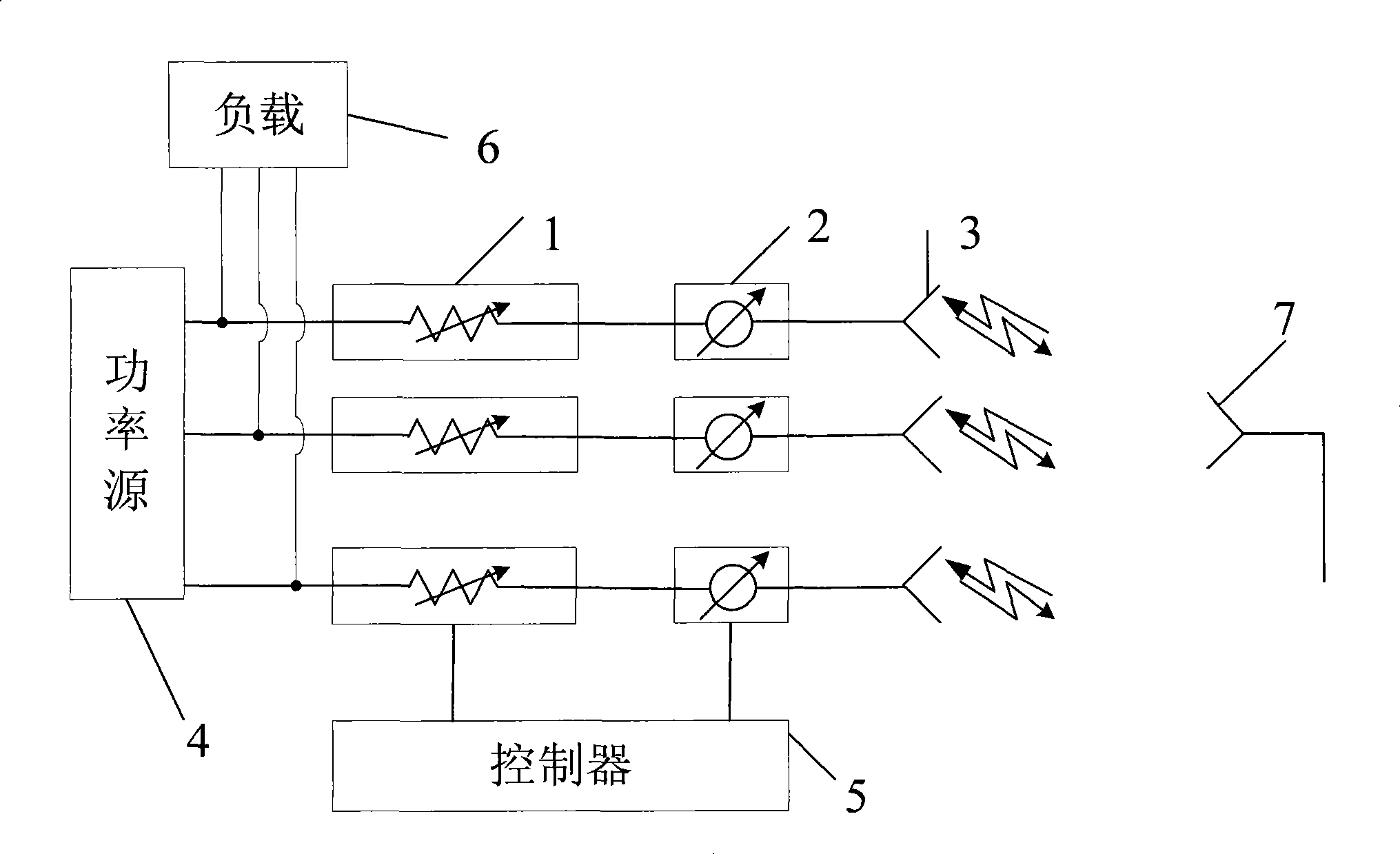
[0033] Such as figure 1 Shown is the structural diagram of the array antenna with variable amplitude and phase. In the figure, 3 is the antenna unit, 1 is the attenuator, and 2 is the phase shifter. By changing the state of the attenuator and the phase shifter, the amplitude and phase of the signal fed to each antenna unit can be changed. This work is performed by the controller 5 To be done.
[0034] 4 is a power source. When the array antenna is in the transmitting mode, the power source feeds each antenna unit through a corresponding attenuator and a phase shifter to transmit array signals. The power source includes a power divider to divide one signal into multiple paths and feed them to each antenna unit. The phase and amplitude of the signals of each antenna unit can be set by the controller to form the required specific shape of the beam and realize beam scanning. At this time, the auxiliary antenna 7 can be set in the far field range of the array antenna. When the a...
PUM
 Abstract
Description
Claims
Application Information