Supercharge Your Innovation With Domain-Expert AI Agents!

Magnetic force torque converter

A torque converter and magnetic technology, applied in the field of torque converters, can solve the problems of large energy loss, low efficiency, complex structure, etc.

Inactive Publication Date: 2009-07-15
刘新广
View PDF0 Cites 6 Cited by
  • Summary
  • Abstract
  • Description
  • Claims
  • Application Information

AI Technical Summary

Problems solved by technology

[0002] The existing hydraulic torque converter has stable torque conversion, but the efficiency is very low and the energy loss is large; the existing mechanical torque converter has higher efficiency than the existing hydraulic torque converter, but it is still too low, and the structure is complex and wears Severe, shock and vibration occur when the torque is changed, and the service life is short

Method used


Image

  • Magnetic force torque converter
  • Magnetic force torque converter
  • Magnetic force torque converter

Examples


Embodiment 1

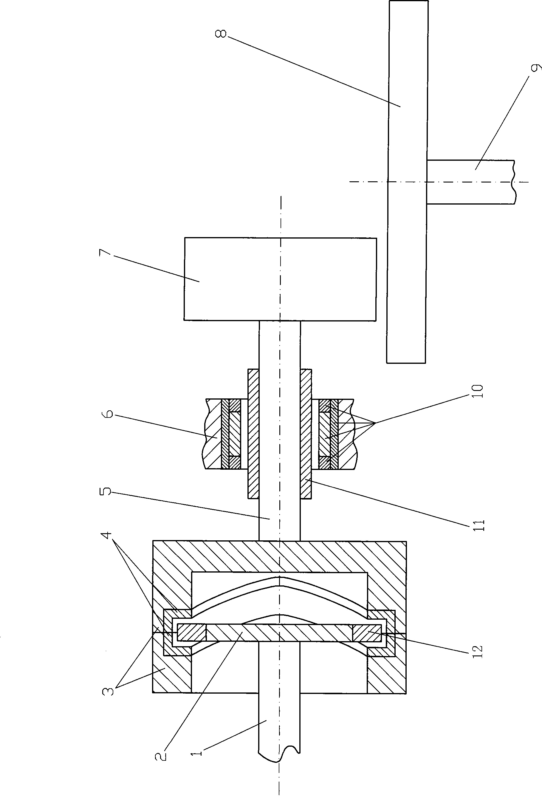
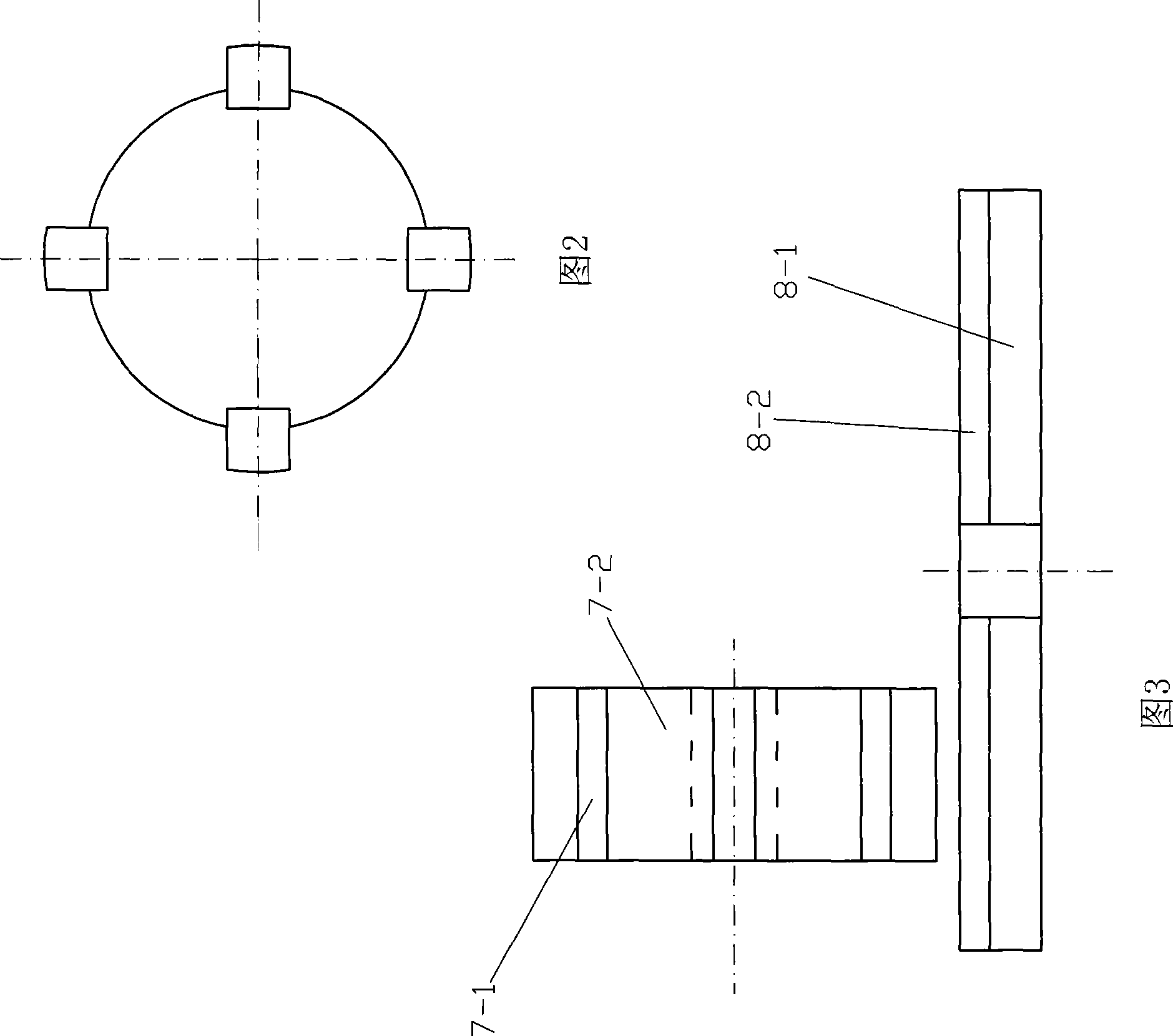
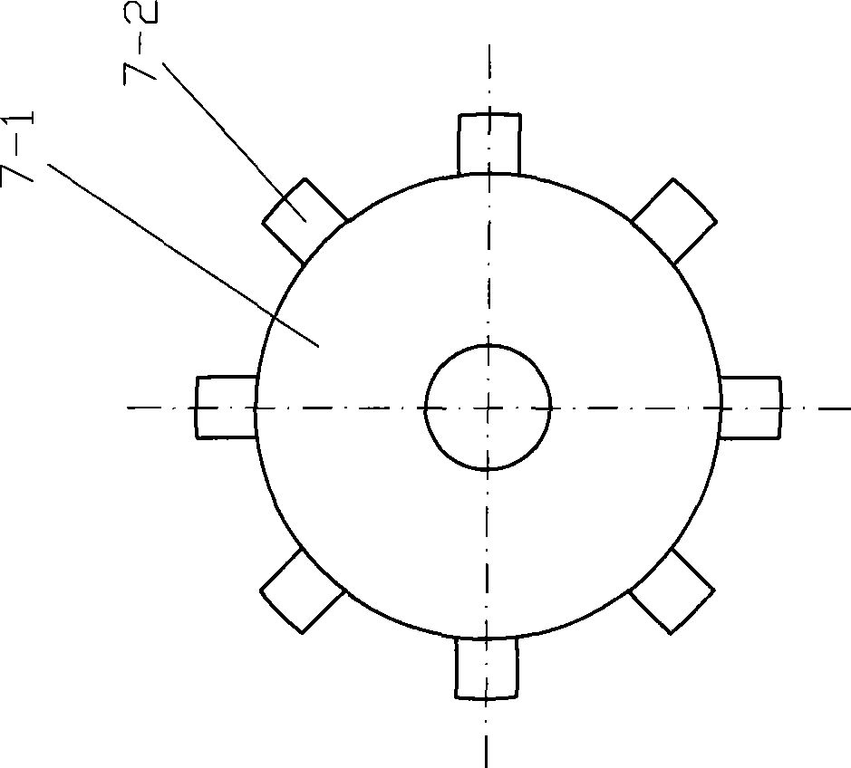
[0046] Such as figure 1 , Figure 2 shows that the right end of the power input shaft 1 is coaxially connected to the disk 2, and several combined permanent magnets 12 are consolidated on the disk 2, and the cylinder 3 combined in the axial direction is arranged, and the first and last phases are formed inside it. Connected wave-shaped combined permanent magnet groove 4, permanent magnet 12 inserts in the permanent magnet groove 4 but leaves a gap of the groove wall of permanent magnet groove 4, and makes permanent magnet 12 and the groove wall of permanent magnet groove 4 opposite to each other, permanent magnet 12 Due to the repulsive force of the permanent magnet groove 4, it is suspended in the permanent magnet groove 4; the transmission shaft 5 is coaxially connected with the right end of the cylinder 3 and the left end of the magnetic transmission wheel 7. When installing, the transmission shaft 5 is coaxial with the shaft 1, and the transmission The magnetic bearing inne...

Embodiment 2

[0057] In Embodiment 1, the magnetic transmission wheel 7 and the magnetic transmission disc 8 can be replaced with a coaxial transmission gear pair transmission mechanism. Such as Figure 15 Figure and Figure 16 As shown, the magnetic transmission wheel 7 is replaced by the ring gear 17, the magnetic transmission disc 8 is replaced by the gear 18 coaxial with the ring gear 17 and meshed with the transmission, and the output shaft 19 is coaxially connected with the right end face of the internal gear 18; The ring gear 17 and the gear 18 are exchanged.


PUM


Abstract

The present invention discloses a magnetic force torque converter, which comprises the following steps: connect a collar plate on the right end of a input shaft coaxially; consolidate a permanent magnet on the collar plate; set a cylinder or a column that combined in axial direction; wave shape permanent magnetic groove that beginning and end connects on the inner or outer circle; insert the permanent magnet into the permanent magnetism groove but leave a gap with groove wall of the permanent magnetism groove and make the permanent magnet faces against homopolar groove wall of the permanent magnetism groove; the drive axle connects with right end of the cylinder or column and the left end of the magnetic drive wheel coaxially; the drive axle is suspendingly supported by magnetic bearings in radial direction; upper end-face of the magnetic driving disc that connects with the output shaft leaves the gap and is disposed on the lower part of the driving wheel; axial cord of the driving disc vertical to axial cord of the driving wheel; when the input shaft drives the permanent magnet rotate, because of magnetic repulsion, the cylinder and the column makes circle auger sport, and the driving wheel will move in radial direction of the driving disc; composite force application point of engaging force changes continuously; when the driving wheel is far from the center of the driving disc, acting moment of torque increases, and inversely decrease to realize automatic torque changing. The present invention is provided with simple structure, smooth and steady torque changing, and high efficiency.

Description

technical field [0001] The invention relates to a torque converter, in particular to a magnetic torque converter. Background technique [0002] The existing hydraulic torque converter has stable torque conversion, but the efficiency is very low and the energy loss is large; the existing mechanical torque converter has higher efficiency than the existing hydraulic torque converter, but it is still too low, and the structure is complex and wears Severe, shock and vibration occur when the torque is changed, and the life is short. Contents of the invention [0003] The invention designs a magnetic torque converter for the purpose of overcoming the defects of the existing torque converter, simplifying the structure and improving the efficiency. [0004] The present invention is realized according to the following technical solutions. [0005] Technical solution one: [0006] Such as figure 1 , Figure 2 shows that the right end of the power input shaft 1 is coaxially connect...

Claims


Application Information

Patent Timeline
Patent Type & Authority Applications(China)
IPC IPC(8): H02K51/00H02K49/10
Inventor 刘新广
Owner 刘新广
Features
  • R&D
  • Intellectual Property
  • Life Sciences
  • Materials
  • Tech Scout
  • Unparalleled Data Quality
  • Higher Quality Content
  • 60% Fewer Hallucinations
Learn More