Shield-arc welding device with aerating device inside tube

A technology of gas shielded welding and inflatable device, applied in welding equipment, welding accessories, arc welding equipment and other directions, can solve the problems of complex structure and complicated operation steps, and achieve the effect of ensuring welding quality

Inactive Publication Date: 2009-07-22
浙江天力久田管业有限公司
View PDF1 Cites 15 Cited by
  • Summary
  • Abstract
  • Description
  • Claims
  • Application Information

AI Technical Summary

Problems solved by technology

The disadvantages of this kind of tube argon arc welding argon filling device are: the structure is relatively complicated, and the parts need to be combined into a whole before it can be used, and the operation steps are cumbersome.

Method used


Image

  • Shield-arc welding device with aerating device inside tube
  • Shield-arc welding device with aerating device inside tube
  • Shield-arc welding device with aerating device inside tube

Examples


Embodiment 1

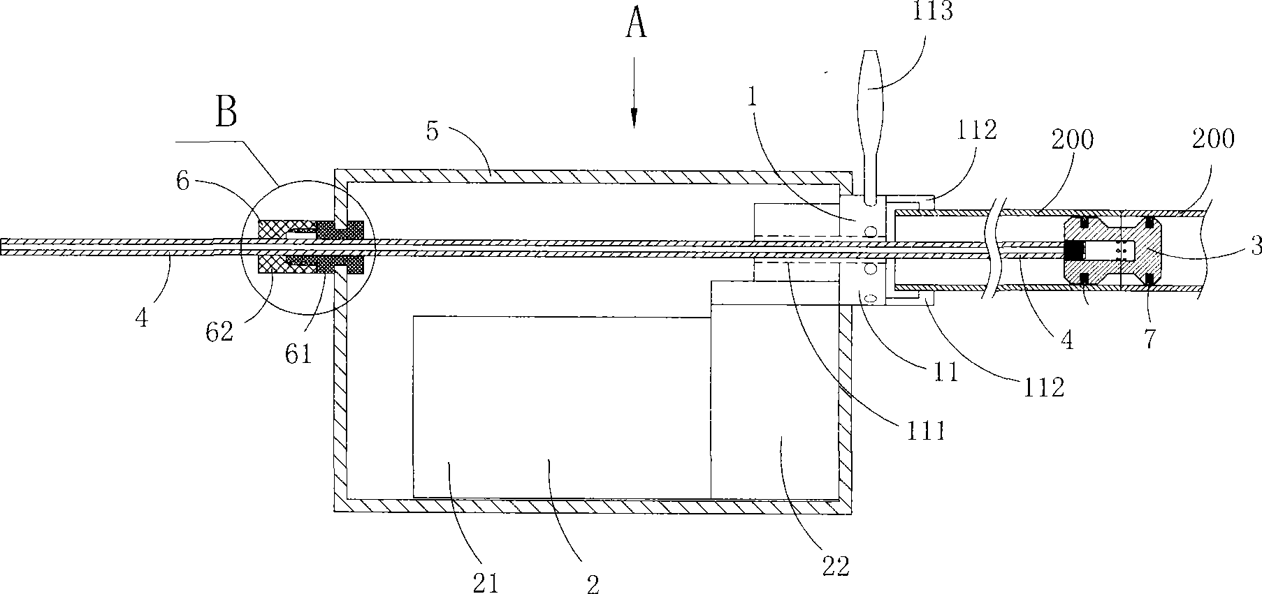
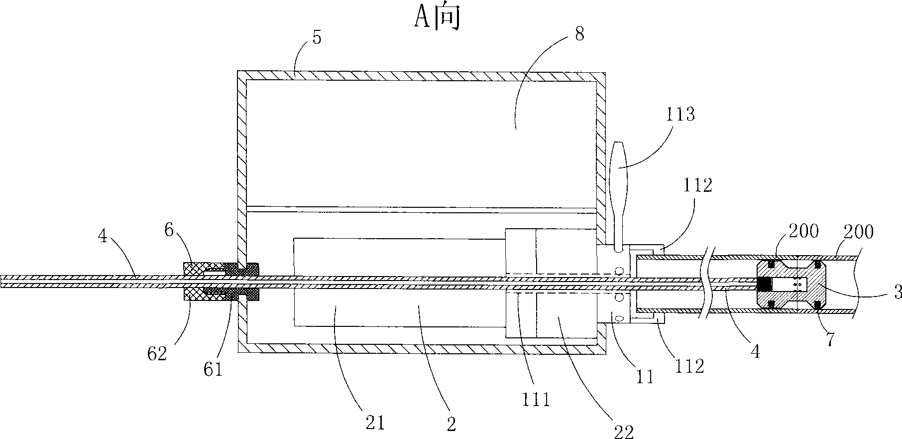
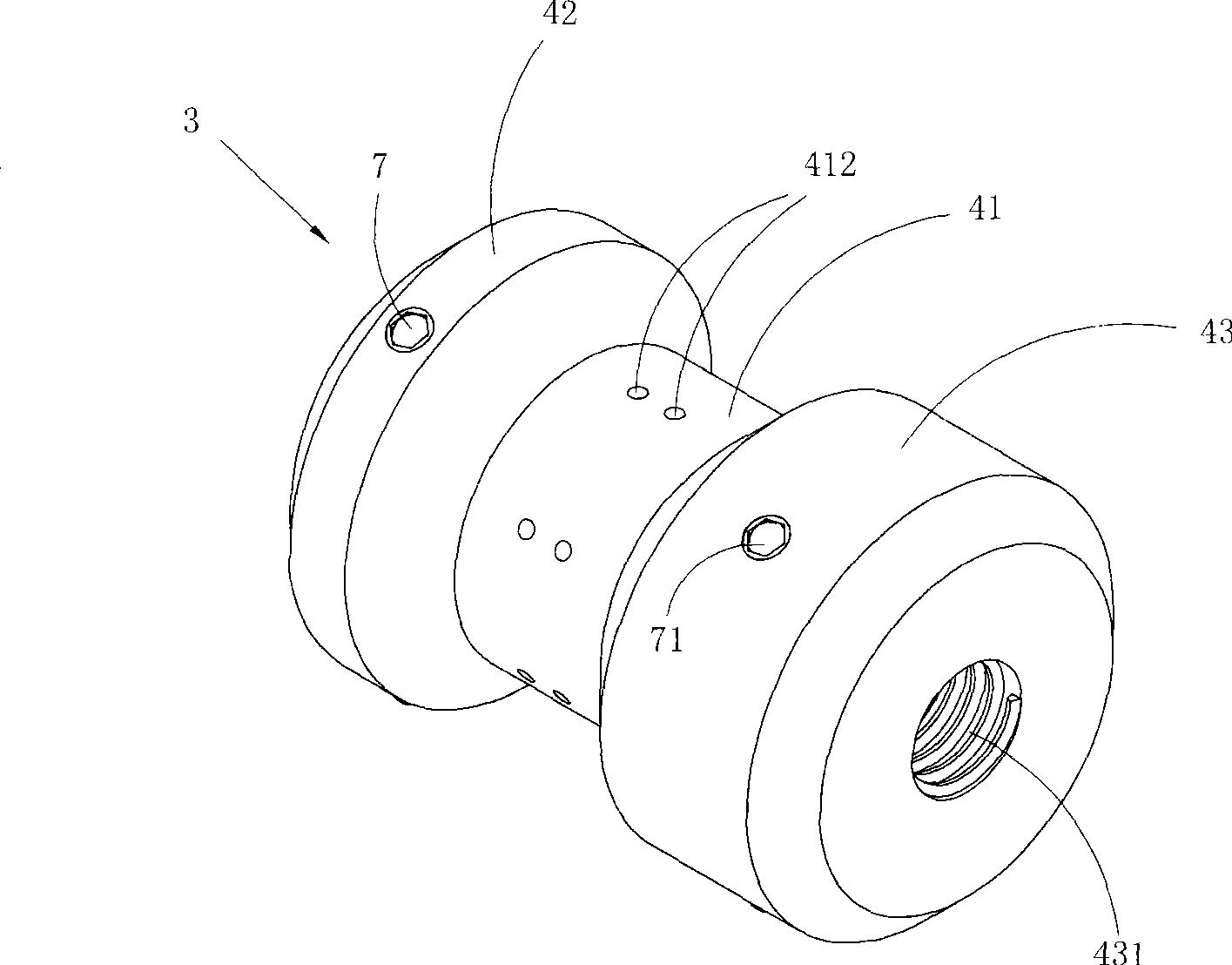
[0041] Figure 1 to Figure 5 A first embodiment of the invention is shown in which, figure 1 It is a structural schematic diagram of the first structure of the present invention; figure 2 yes figure 1 The A-direction view of the gas shielded welding device with the gas filling device in the tube shown; image 3 yes figure 1 A schematic diagram of the three-dimensional structure of the gas filling device in the tube in the gas shielded welding device with the gas charging device in the tube shown; Figure 4 yes image 3 Schematic diagram of the cross-sectional structure of the inflatable device shown in the tube; Figure 5 yes figure 1 The partial enlarged schematic diagram of B.

[0042] This embodiment is a gas shielded welding device with an inflatable device in the pipe, see figure 1 and figure 2 , including: a locking device 1 with a chuck 11 for clamping the pipe to be welded; a drive mechanism 2 for driving the chuck 11 to rotate; Gas inflating device 3 in th...

Embodiment 2

[0055] Figure 6 It is a schematic diagram of the half-section structure of the inflatable device in the tube in the second structure of the present invention, showing the second specific embodiment of the present invention.

[0056] This embodiment is basically the same as Embodiment 1, the difference is: see Figure 6 , In the inflatable device 3 in the present embodiment, two rows of air outlet holes 412 are arranged on the outer surface of the inflatable part 41 along the circumferential direction. In addition, the mounting hole 44 on the first blocking portion 42 is a through hole provided with an internal thread, each of the drag reducing devices 7 includes two balls 71, a spring 72 providing elastic support for the balls, and two outer Thread retaining ring 73; According to spring 72 inside, ball 71 is arranged in the mounting hole 44 in the order that spring and ball are outside successively, and described two external thread retaining rings 73 block two entrances of ...

Embodiment 3

[0058] Fig. 7 and Fig. 8 have shown the third specific embodiment of the present invention, wherein Fig. 7 is a kind of three-dimensional structure schematic diagram of the inflatable device in the pipe in the third structure of the present invention; Fig. 8 is the half of the inflatable device in the pipe shown in Fig. 7 Schematic diagram of the sectional structure.

[0059] This embodiment is basically the same as Embodiment 1, except that: the first blocking portion 42 and the second blocking portion 43 are provided with installation holes 44, each of the drag reducing devices 7 only includes balls 71, the The ball 71 is rolled and embedded in the installation hole 44 .


PUM


Abstract

The invention discloses a gas shielded welding device with an air charging device inside a tube. The gas shielded welding device comprises a locking device with a chuck for clamping a pipeline to be welded, a drive mechanism for driving the chuck to rotate, the air charging device inside the tube for charging protective gas from a pore space of the pipeline to be welded, and an air charging pipe communicated with the air charging device inside the tube. The gas shielded welding device has the advantages that the device has a semiautomatic structure and convenient operation, and can improve welding quality.

Description

technical field [0001] The invention belongs to the technical field of gas shielded welding, and in particular relates to a gas shielded welding device with an inflatable device in a pipe. Background technique [0002] When performing gas shielded welding on pipes, the traditional method is to connect two pipes to each other, plug one end with a plug, and open the other end, and fill the whole pipe with shielding gas for air replacement. However, due to certain materials When the pipeline is welded, the oxygen content requirement is very low, and this method of blocking one end and opening the other is difficult to meet the requirements; in addition, if the existing plug encounters pipeline elbows, tees and other pipelines, it is difficult to install and remove; At the same time, this method of filling the shielding gas in the whole process for gas shielded welding consumes a large amount of shielding gas, and the waste is serious, which is not conducive to reducing the cons...

Claims


Application Information

Patent Timeline
Patent Type & Authority Applications(China)
IPC IPC(8): B23K9/16B23K9/32
Inventor 阮继成
Owner 浙江天力久田管业有限公司
Why Eureka
Try Eureka