Surface mount antenna and antenna module

一种表面安装型、天线模块的技术,应用在天线、天线耦合、谐振天线等方向,能够解决放射导体放射特性恶化、困难等问题,达到兼顾宽频带化、兼顾小型化的效果

Inactive Publication Date: 2009-07-22
TDK CORPARATION
View PDF2 Cites 3 Cited by
  • Summary
  • Abstract
  • Description
  • Claims
  • Application Information

AI Technical Summary

Problems solved by technology

In addition, since the open ends of the radiation conductors are formed at different positions, it is difficult to mount them in a preferred direction for making the radiation characteristics of the radiation conductors good when mounted on a circuit board.
That is, when the radiation characteristics of one radiation conductor are optimally mounted, the radiation characteristics of the other radiation conductor will deteriorate.

Method used


Image

  • Surface mount antenna and antenna module
  • Surface mount antenna and antenna module
  • Surface mount antenna and antenna module

Examples


no. 1 approach

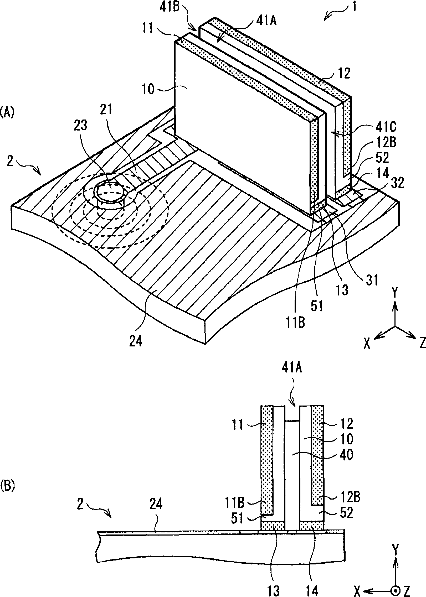
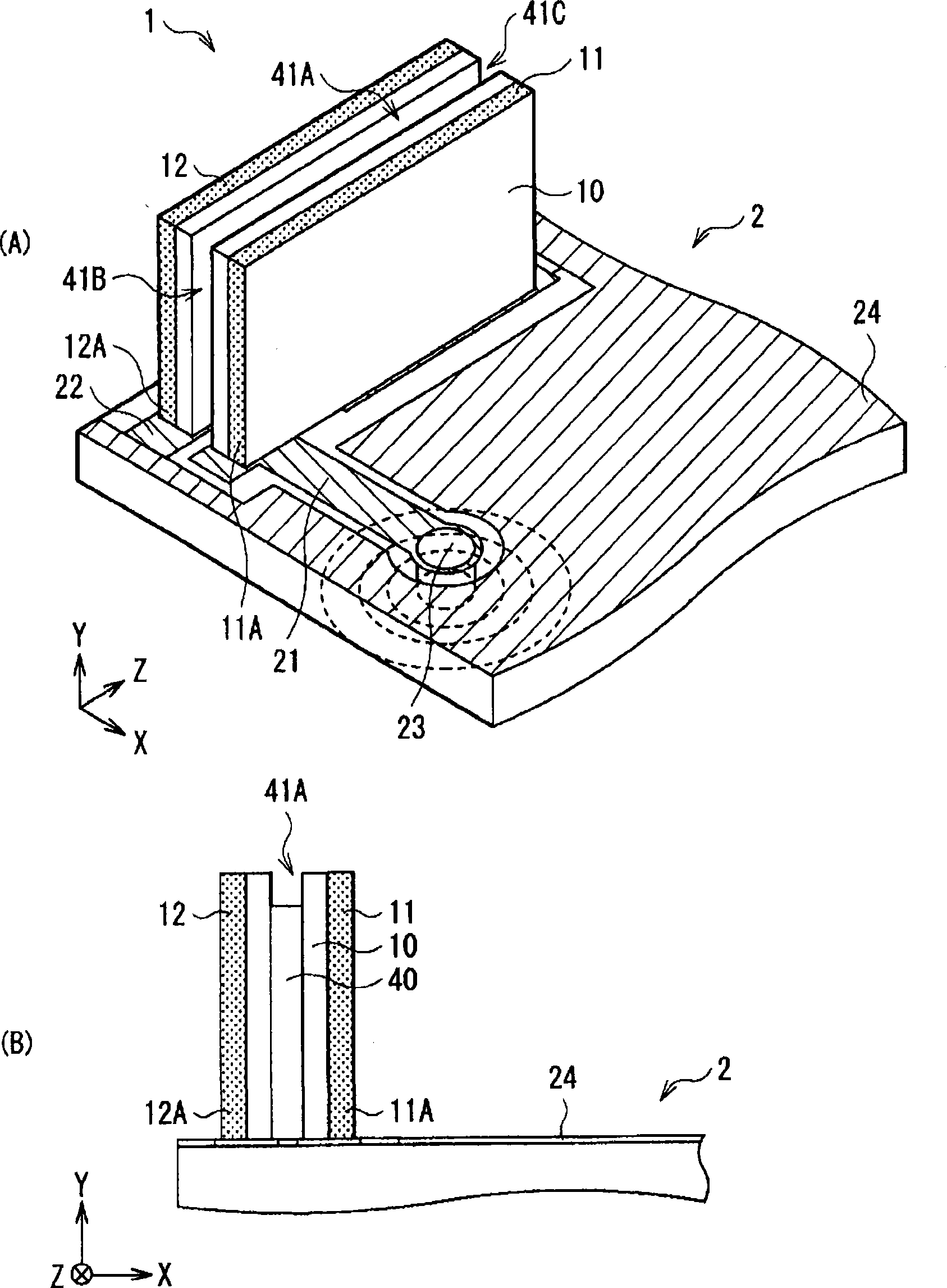
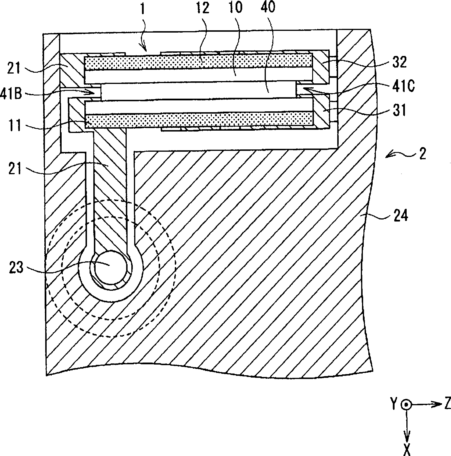
[0065] figure 1 (A) and (B) show a configuration example of the antenna module to which the surface mount antenna 1 of the present embodiment is mounted. in particular, figure 1 (A) shows a state in which the antenna module is viewed obliquely from the radiation side (open end side) of the surface mount antenna 1, figure 1 (B) shows the side surface of the radiation side. also, figure 2 (A) shows a state in which the antenna module is viewed obliquely from the feeding side of the surface mount antenna 1, figure 2 (B) shows the side surface of the power supply side. also, image 3 The structure of the upper surface of the antenna module is shown. Figure 4 show figure 1 (A) See-through state of the structure shown. also, Figure 5 An equivalent circuit diagram of the antenna module is shown.

[0066] This antenna module includes: a plate-shaped circuit board 2 ; and a surface mount antenna 1 mounted on the upper surface of the circuit board 2 . On the upper sur...

no. 2 approach

[0085] Next, a second embodiment of the present invention will be described. Also, substantially the same structural parts as those of the antenna module of the above-mentioned first embodiment are given the same symbols, and descriptions thereof are appropriately omitted.

[0086] Figure 7 (A) and (B) show a configuration example of the antenna module to which the surface mount antenna 1A of the present embodiment is mounted. in particular, Figure 7 (A) shows a state in which the antenna module is viewed obliquely from the radiation side (open end side) of the surface mount antenna 1A, Figure 7 (B) shows the side surface of the radiation side. also, Figure 8 (A) shows a state in which the antenna module is viewed obliquely from the feeding side of the surface mount antenna 1A, Figure 8 (B) shows the side surface of the power supply side. also, Figure 9 The structure of the upper surface of the antenna module is shown.

[0087] In the surface mount antenna 1 of t...

no. 3 approach

[0091] Next, a third embodiment of the present invention will be described. Also, substantially the same components as those of the antenna modules of the above-described embodiments are given the same symbols, and their descriptions are appropriately omitted.

[0092] Figure 10 (A) and (B) show a configuration example of the antenna module to which the surface mount antenna 1B of the present embodiment is mounted. in particular, Figure 10 (A) shows a state in which the antenna module is viewed obliquely from the radiation side (open end side) of the surface mount antenna 1B, Figure 10 (B) shows the side surface of the radiation side. also, Figure 11 (A) shows a state in which the antenna module is viewed obliquely from the feeding side of the surface mount antenna 1B, Figure 11 (B) shows the side surface of the power supply side. also, Figure 12 The structure of the upper surface of the antenna module is shown.

[0093] The surface mount antenna 1B of this embod...


PUM


Abstract

A surface mount antenna and an antenna module with small size and broadband are provided. In the surface mount antenna, the part ( a substrate upper part(41A) and a substrate side part(41B)(41C)) between a power supply radiating conductor(11) and a non-power-supply radiating conductor(12) is in the groove shape. The part in the groove shape is an air layer, thus being as the lower-dielectric-constant area. The area with the dielectric constant lower than that of the dielectric substrate 10 is arranged among the power supply radiating conductors, thus reducing the electromagnetic coupling amount among the radiating conductors, further making the resonant frequencies of all radiating conductors similar in the multiple resonance forming range to realize the broadband.

Description

technical field [0001] The present invention relates to a surface-mounted antenna and an antenna module used in wireless communication devices such as mobile phones, for example. Background technique [0002] In the past, such as Figure 28 As shown, there is known a surface mount antenna having a structure in which a feeding radiation conductor 101 as a main radiation element (feeding element) and a parasitic radiation conductor 102 as a parasitic element are arranged adjacent to the surface of a rectangular parallelepiped dielectric substrate 100 . One end 101A of the power feeding radiation conductor 101 is connected to the signal supply source 103 to receive power from the one end 101A side, and the other end 101B side becomes an open end (signal radiation side). One end 102A of the passive radiation conductor 102 is short-circuited, and the other end 102B side becomes an open end (signal radiation side). The feeding radiation conductor 101 and the parasitic radiation c...

Claims


Application Information

Patent Timeline
Patent Type & Authority Applications(China)
IPC IPC(8): H01Q1/38H01Q5/01H01Q9/30H01Q1/24H01Q1/52H01Q5/10
CPCH01Q9/42H01Q1/243H01Q1/38H01Q5/00H01Q5/0062H01Q5/378
Inventor 外间尚纪张原康正远藤谦二大桥武
Owner TDK CORPARATION
Why Eureka
Try Eureka